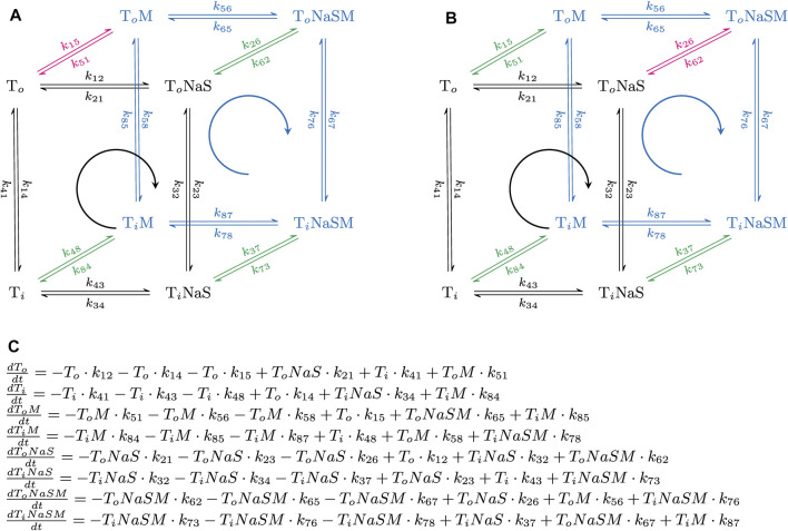
FIGURE 1.
Simplified reaction schemes of the transport cycle of a solute carrier in the absence and presence of an allosteric modulator. (A,B) show the reaction diagrams of the kinetic models, which were used to emulate the action of a positive and a negative allosteric modulator, respectively. To and Ti are the substrate-free outward (OF)- and substrate-free inward-facing (IF) conformations. ToNaS is the (co)-substrate bound OF state and TiNaS the (co)-substrate bound IF state. ToM, TiM, ToNaSM and TiNaSM are the modulator-bound counterparts. The reaction diagrams are comprised of one reaction loop in the front (indicated in black) and one in the rear (indicated in blue). The two loops, which represent the transport cycle of a hypothetical solute carrier in the absence (front loop) and presence (rear loop) of the modulator (M), were biased in the forward direction (i.e., clockwise) by setting the concentration of Na+ to 150 mM on the extracellular and to 0 mM on the intracellular side. The red and green arrows indicate the high and low affinity binding reaction(s) of the modulator, respectively. In (A), the modulator was assumed to bind with higher affinity to the To state. In (B), the modulator was assumed to bind with higher affinity to the ToNaS state. (C) System of differential equations, which underlies the reaction schemes in (A,B). Each of the displayed equations defines the time-dependent change in state occupancy of one of the eight states specified in (A,B).

