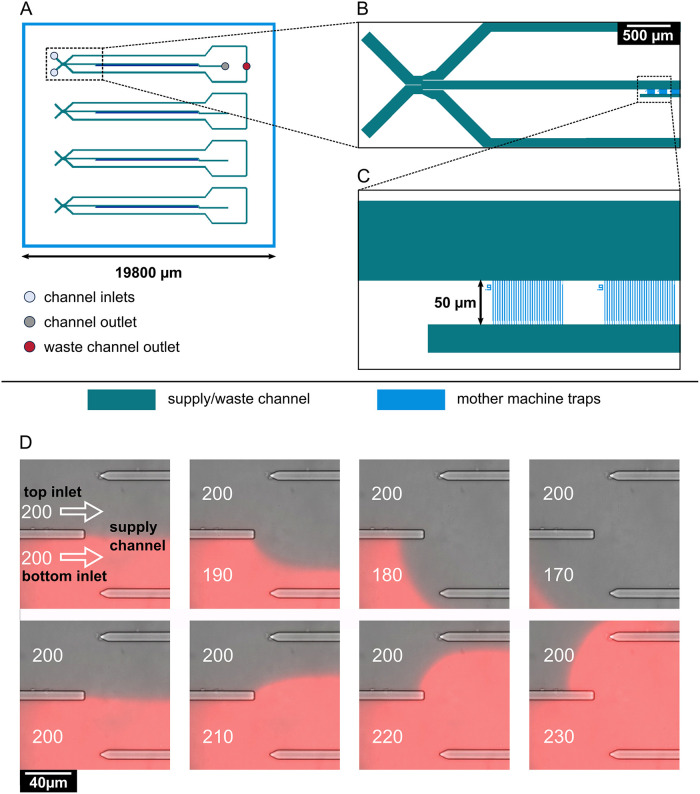
Fig 5. Design and operation of the microfluidic mother machine device.
(A) Schematic overview of the chip layout, featuring four independent supply channels (green) for cell inoculation and media supply. (B) Detailed view of the area marked by a rectangle in (A), showing the switching junction and a part of the mother machine cultivation sites (blue). The junction is formed by two inlets, leading to one central supply channel. Control of pressure at each inlet allows for prioritization of one medium over the other through the supply channel, and, ultimately, the mother machine cultivation sites. Residual medium flows out through waste channels located to each side of the central supply channel. Medium flowing through the supply channel exits the chip through one outlet. (C) Detailed view of the area marked in (B) by a rectangle, showing the mother machine cultivation sites. Each of the four channels contains 57 mother machine cultivation sites, each of which contains 30 mother machine traps with widths of either 0.9, 1, or 1.1 μm. The mother machine traps feature a 0.3 μm wide constriction on the bottom, preventing the mother cell from exiting the trap while allowing perfusion of the medium. The supply channels (green) are 8 μm in depth, the mother machine traps (blue) are 0.8 μm in depth. (D) On-chip medium switching visualized by merged phase contrast and mCherry images of the channel junction. Media are supplied through separate inlets (top and bottom), which are separated in the center of the channel by a PDMS barrier. The direction of flow is indicated by white arrows. Water was supplied through the top inlet, while a 0.2 μM sulforhodamine B solution was supplied through the bottom inlet, visualizing the flow pattern in the junction. The pressure at the top inlet was kept constant at 200 mbar. Depending on the pressure set at the bottom inlet, it is possible to select which one of the two media flows into the central supply channel to the mother machine growth sites.

