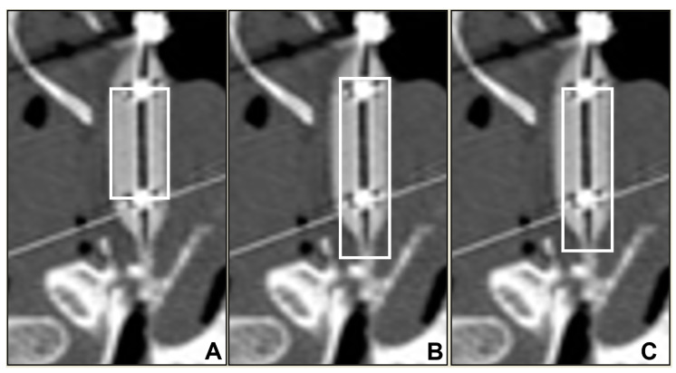
Figure 3.
Example of how vertical ROI boxes (white rectangle) (A)—small; (B)—longest; (C)—long) are placed in an inflated balloon-guided ET lumen (Ear 1). Outline of the small ROI boxes (A) was formed to include the main body of the inflated balloons, to include the 6 mm width in the full 16 mm cylindrical segment. Radiopaque markers were used as markers, and short sides of the ROI boxes were set to cross these markers. This segment of the balloon represents the section of the ET that was subjected to the maximum dilation pressure. Proximal and distal ends of the balloons had conical sections which had a relatively less dilation force on the tissues. In order to include a longer section of the ET in the ROI, and to differentiate the effect of these cylindrical and conical sections of the balloons on the tissues, the longest ROI box (B) was extended to the end of the balloon towards the middle ear (bottom of the images) and towards the nasopharyngeal end of the balloon (top of the images) while avoiding inclusion of nasopharyngeal air column. The long ROI (C) was then formed by retracting the box by 5 pixel units from the middle ear and the NP end.

