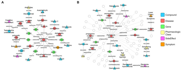
Figure 9.
PD patient specific networks from SPOKE (A) corresponds to a patient correctly diagnosed by both clinician and SPOKE model. (B) corresponds to a patient correctly diagnosed only by SPOKE model. Triangle shaped nodes represent clinical concepts present in patient’s EHR chart and hence the entry points to SPOKE. Circle shaped nodes are the non-entry points. Nodes are connected by edges whose names are shown in the figure. To reduce the complexity of the network (B), certain nodes and edges are grayed out based on manual inspection. Legend shows the color code for each node type in the network.

