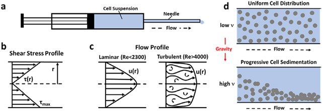
Figure 1:
Schematics detailing biomechanical concepts relevant to injection of cell suspensions through syringe-needle systems. (a) Diagram of the syringe-needle system showing flow path through needle with inner radius r. (b) Shear stress profile as occurs within needle during injection. Maximum Shear Stress occurs at the needle wall, decreasing linearly as the center axis of the cylindrical needle is approached. (c) Reynold’s number (Re) is used to predict laminar or turbulent flow profiles, which exhibit unique velocity profiles (u(r)) with respect to needle dimensions. (d) Sedimentation velocity , which is largely dependent on and inversely related to dynamic viscosity of the delivery vehicle, determines cell distribution throughout the injection process. Cell sedimentation during injection contributes to inconsistent dosing, unpredictable cell distribution, and clogging of needle.

