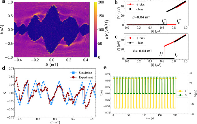
Fig. 3. Josephson diode effect.
a Differential resistance map of Device 1 as a function of bias current and applied out-of-plane magnetic field, B. b I–V characteristics for both bias directions at B = 0.04 mT. c Identical measurement as b, but at B = − 0.04 mT. The current sweeps always start at I = 0. d Diode efficiency factor Q as a function of B obtained from experiment (red circles) and simulations (blue squares). e Measured voltage drop (shown in green) for an applied square wave current pulse (shown in yellow).

