
Extended Data Fig. 1. Characterization of the HAP1-CTCFdegron.
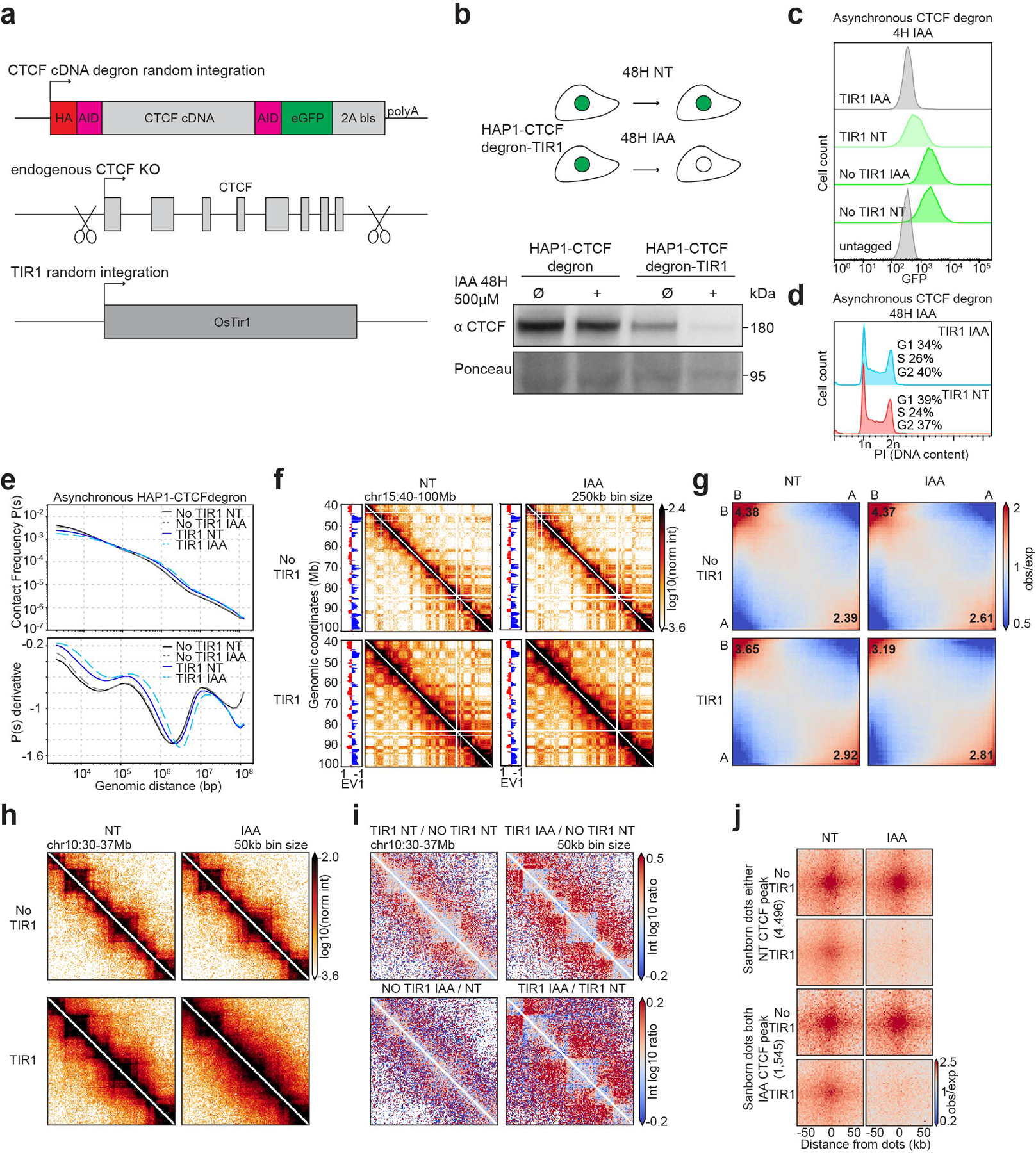
a, Schematic representing the strategy used to construct the HAP1-CTCFdegron-TIR1 cells.
b, Schematic representing CTCF depletion in HAP1-CTCFdegron-TIR1 cells (top). Western blot against CTCF in HAP1-CTCFdegron cells and in HAP1-CTCFdegron-TIR1 cells without/with auxin (NT and IAA). Ponceau is shown for loading control (bottom).
c, Flow cytometry for GFP in HAP1-CTCFdegron and HAP1-CTCFdegron-TIR1 cells without/with auxin.
d, Flow cytometry for HAP1-CTCFdegron-TIR1 cells without/with auxin stained with Propidium Iodide (PI) to assess the DNA content for cell cycle analysis.
e, Hi-C contact frequency as a function of genomic distance, P(s) (top) and its derivative dP/ds (bottom) for HAP1-CTCFdegron and HAP1-CTCFdegron-TIR1 cells without/with auxin.
f, Hi-C contact heatmaps at 250kb resolution with the corresponding track of the first Eigenvector (EV1) across chromosome 15 for HAP1-CTCFdegron and HAP1-CTCFdegron-TIR1 cells without/with auxin.
g, Genome-wide saddle plots of Hi-C data binned at 100kb resolution for HAP1-CTCFdegron and HAP1-CTCFdegron-TIR1 cells without/with auxin. The compartment strengths are indicated in the corners.
h, Hi-C contact heatmaps at 50kb resolution for a 7Mb region on chromosome 10 for HAP1-CTCFdegron and HAP1-CTCFdegron-TIR1 cells without/with auxin.
i, Differential interaction heatmaps for HAP1-CTCFdegron and HAP1-CTCFdegron-TIR1 cells.
j, Dot pileups for dots characterized in HAP1 cells that have a CTCF peak in either anchor in the Non-Treated sample (4,496 dots) and that have a CTCF peak in both anchors in the auxin sample (1,545 dots) for HAP1-CTCFdegron and HAP1-CTCFdegron-TIR1 cells without/with auxin. The dots were aggregated at the center of a 100kb window at 2kb resolution.