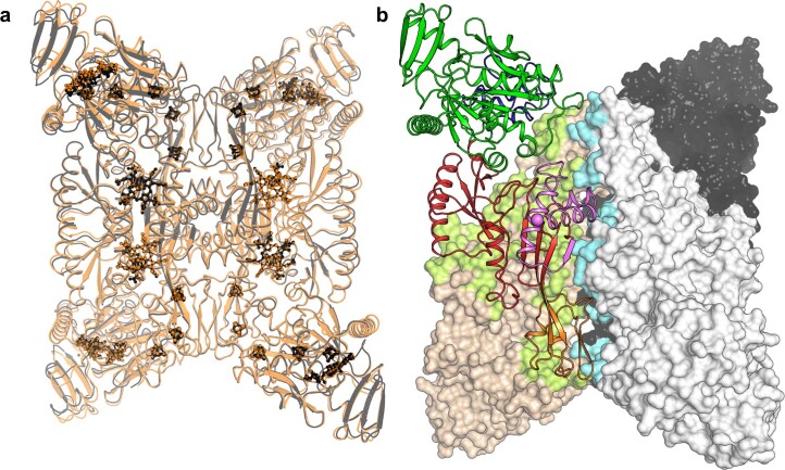
Extended Data Fig. 3. Homotetrameric arrangement of Fsr.
a, Superposition of MtFsr (black) with MjFsr (orange, rmsd of 0.456 Å for 544-Cα aligned). Ligands are shown in balls and sticks and coloured in black and orange for MtFsr and MjFsr, respectively. b, Surface area involved in the oligomerization in Fsr. Monomers of MtFsr are shown in surface representation, with one monomer being displayed in cartoon and coloured by its domain composition: the N-terminal ferredoxin domain in dark blue, F420H2-oxidase in green, the sulfite reductase domain in red and its inserted ferredoxin domain in orange. The C-terminal segment involved in the oligomerization is coloured in light pink with the C-terminus highlighted as a ball. The monomer-monomer contacts are shown as a green surface and contacts to the adjacent dimer are visualized by a cyan surface. The basic monomer-monomer interface of 2,902-Å2 for MtFsr and 2,971-Å2 for MjFsr is established by the sulfite reductase domain and the two additional ferredoxin domains. The C-terminal part of the sulfite reductase domain (562–618 in MtFsr, 562–620 in MjFsr), the second ferredoxin domain and the loop 171–189 of the F420H2-oxidase domain generate the dimer-dimer interface, totalling an area of 3,055-Å2 for MtFsr and 3,037-Å2 for MjFsr. Most of these contacts involve salt bridges. In MjFsr, the tetrameric structure is supported by two divalent cations, modelled as calcium ions that are each coordinated by a conserved aspartate from the opposite monomers (Asp511 and water molecules)56.

