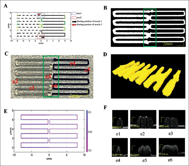
Figure 10.

Single-layer scaffold path for design 2 and printing results. (A) Designed path, where the solid line is the printing path for silica gel-B, and the dotted line is the printing path for silica gel-W. (B) Projection image from OCT data. (C) Printed result. (D) OCT data reconstruction map of the box area in (C). (E) Layer thickness distribution along the path. (F) Cross-sectional images from OCT data at different positions.
