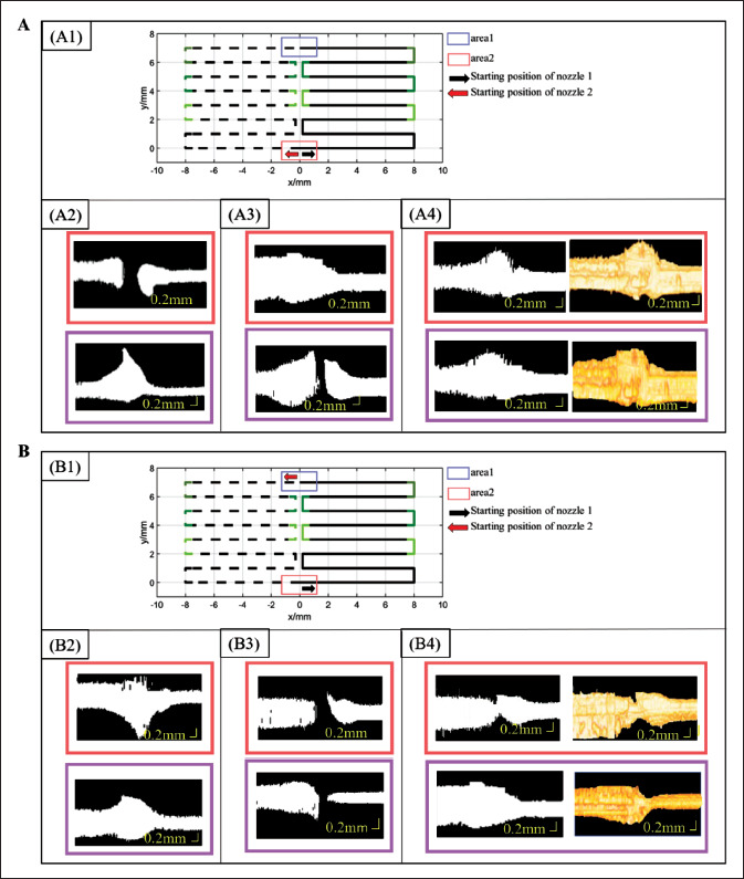
Figure 8.

Experimental results of time-related nozzle control model. (A) Experimental results of nozzle control Model 1. A1 is the designed path, where the solid line is the printing path for silica gel-B, and the dotted line is the printing path for silica gel-W; A2 is OCT data projection map of area 1 and area 2 at initial state; A3 is OCT data projection of area 1 and area 2 at initial control state; A4 is OCT data projection map and reconstruction map of area 1 and area 2 after optimization. (B) Experimental results of nozzle control Model 2. B1 is the designed path, where the solid line is the printing path for silica gel-B, and the dotted line is the printing path for silica gel-W; B 2 is OCT data projection map of area 1 and area 2 at initial state; B3 is OCT data projection of area 1 and area 2 at initial control state; B4 is OCT data projection map and reconstruction map of area 1 and area 2 after optimization.
