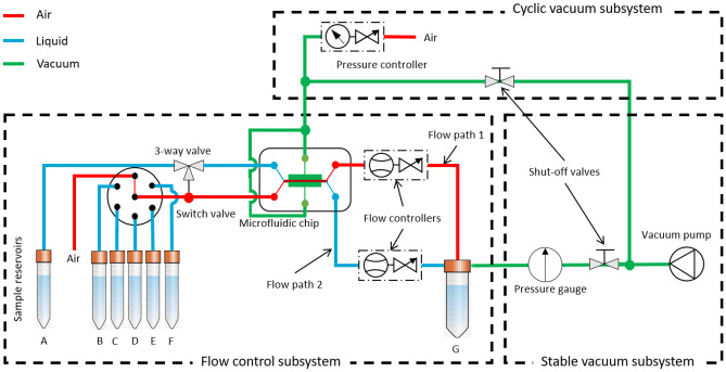
Fig. 2.
Schematic diagram of the fluid handling system, consisting of three subsystems: 1) a stable vacuum subsystem, 2) a flow control subsystem, and 3) a cyclic vacuum subsystem. 1) The stable vacuum subsystem generates the necessary under-pressure to drive fluids in the system. The shut-off valves separate the vacuum pump from different subsystems. 2) The flow control subsystem contains sample reservoir tubes A to F kept at ambient pressure and a waste reservoir tube G at vacuum. The vacuum in tube G enables the aspiration of fluid samples from different reservoirs to the waste reservoir while passing through the switch valve, the microfluidic chip, and flow controllers. For two cell chambers (Fig. 1), there are two fluid flow paths in the chip. The fluid flow rate in both flow paths is controlled separately by controlling the valve in the flow controllers (compatible with both gas and liquid). The fluid is routed in both channels by a switch valve and a 3-way valve. 3) The cyclic vacuum subsystem is used to control the stretching of the membrane separating two cell chambers. The shut-off valve to the flow control subsystem is closed, and the shut-off valve to the cyclic vacuum subsystem is opened. The pressure controller provides the desired frequency cycles of the vacuum

