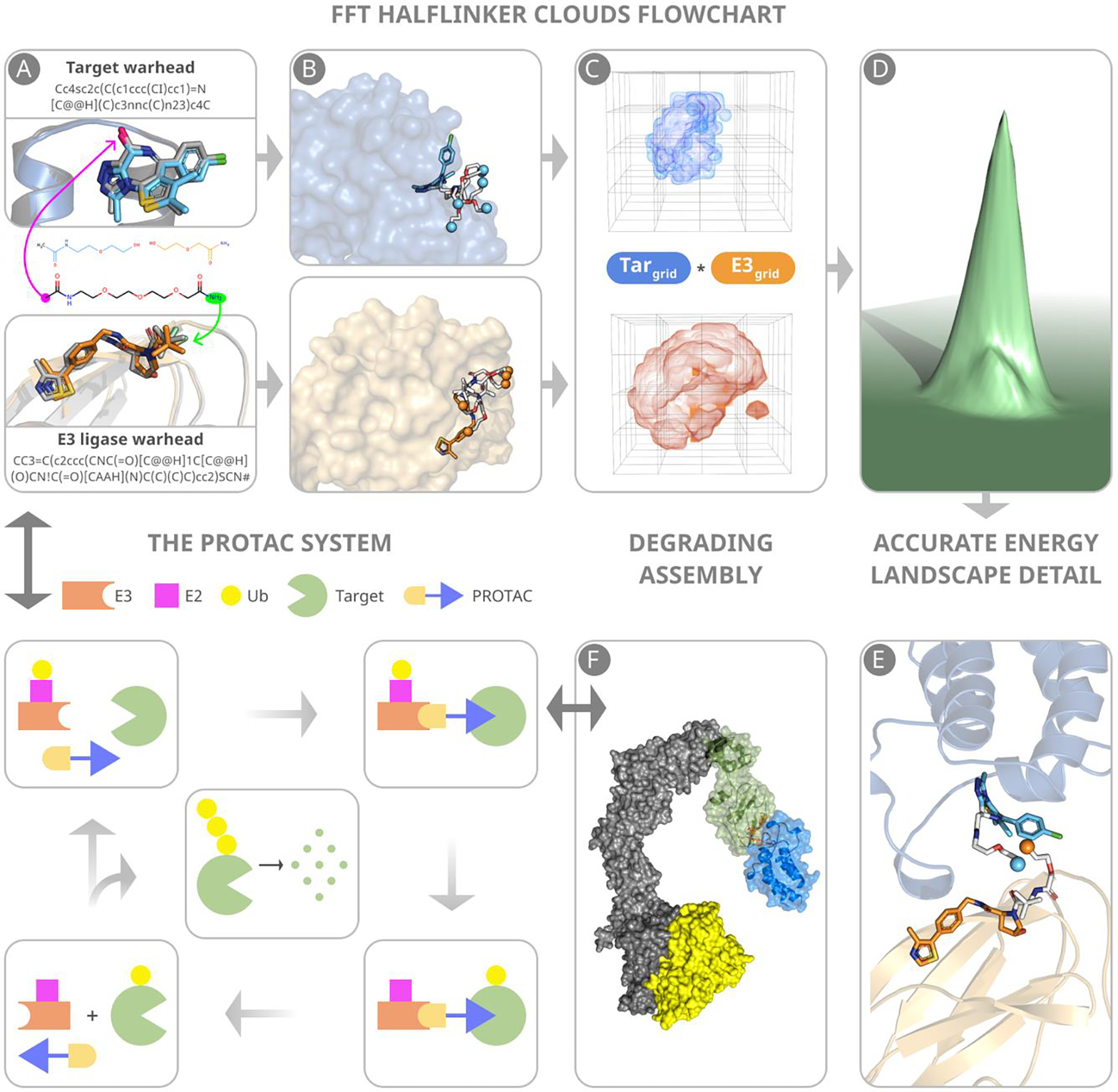
Figure 1.

Main steps of predicting PROTAC structures. (A) Warheads are docked to component proteins. Green and magenta arrows indicate attachment points to the E3 ligase and target warheads, respectively. (B) Half-linker conformations are generated and attached to each protein-bound warhead. The small colored spheres represent the half-linker end points. In the VHL:MZ1:BRD4BD2 (PDB ID: 5T35) complex shown, the BRD4 warhead and the end points of the attached half-linkers are depicted in cyan, and the VHL warhead and the end points of the attached half-linkers are in orange. (C) Generating favorable protein-protein poses that have half-linker ends placed sufficiently close to each other. (D) Selection of low energy poses. (E) A resulting pose with half-linker end points in close proximity before connecting the half-linkers. (F) The VHL–ElonginC–ElonginB–Cul2–Rbx1 structural assembly with the CRL2VHL complex shown in blue. The assembly includes a ubiquitin-like protein (ULP), shown in yellow, separated by a favorable distance to facilitate transfer of ubiquitin to the target. The figure also include a schematic outline of the PROTAC system.
