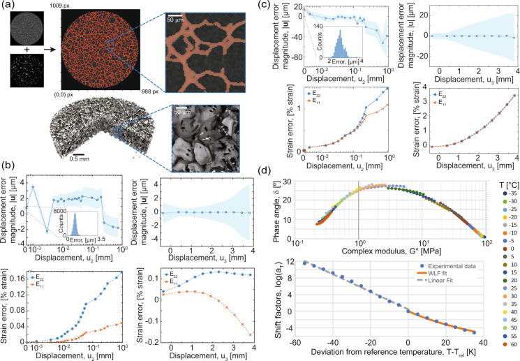
Fig. 6.
Data validations for the assorted techniques. (a) (Top) Example grayscale reconstruction slice with binarization overlay. Inset Magnified region to show detail. Some faint features are missed, but overall the binarization accurately traces the material phases seen in the grayscale image, and (bottom) a similar view showing the 3D model based on the binarized image with magnified inset. (b) Rigid body motion displacement noise for quasi-static rate experiment displacements (top row) and strains (bottom row) in the in-plane (u2) and out-of-plane (u3) directions. The first two in-plane motions (0.001 mm and 0.002 mm) are at the displacement noise floor of the actuator. The actuator error dominates the total measurement error. (c) Rigid body motion displacement noise for intermediate rate experiment displacements (top row) and strains (bottom row) in the in-plane and out-of-plane directions. For (b,c) shaded regions represent one standard deviation of displacement above and below the mean. (d) (Top) The Van Gurp-Palmen plot of phase angle and (bottom) the Williams-Landal-Ferry and Arrhenius fits of the horizontal shift factors.

