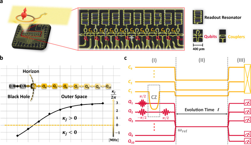
Fig. 1. On-chip analog black hole.
a False-color image of superconducting processor and schematic analog black hole. Ten transmon qubits, Q1 ~ Q10, shown as crosses, are integrated along a chain with nearest-neighbor couplings. Each nearest-neighbor two qubits are coupled via a coupler, C1 ~ C9, realized by a transmon with only a flux bias line. All the transmons are frequency-tunable, but only the qubit has the XY control line and readout resonator. The schematic image represents the background of curved spacetime simulated by this superconducting chip. The red cartoon spin located at the upper-left denotes the evolution of one quasi-particle that is initially in the black hole and the outward-going radiation. b Schematic representation of the site-dependent effective coupling strengths κj. In the experiment, the coupling κj is designed according to Eq. (3). There is a boundary analogous to the event horizon of a black hole, where the coupling changes its sign at site Q3. Thus qubits Q1 and Q2 can be considered as the interior of the black hole, Q3 is at the horizon, and Q4–Q10 are in the outside black hole. c Experimental pulse sequence for observing dynamics of entanglement, which consists of three parts, i.e., (I) initialization, (II) evolution, and (III) measurement. For the initialization (I), we prepare an entangled Bell pair on Q1Q2 by combining several single-qubit pulses and a two-qubit control-phase (CZ) gate. At the left boundary of region (II), the curved (or flat) spacetime forms. Then the system will evolve according to the corresponding κj in the Hamiltonian for a time t. In region (III), we perform the state tomography measurement.

