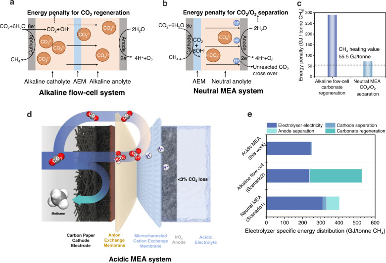
Fig. 1. Schematic illustration and techno-energy analysis of different systems.
Schematic figure of (a) alkaline flow-cell system and (b) neutral MEA system. AEM, anion exchange membrane. MEA, membrane electrode assembly. c Energy penalty of CO2 regeneration from carbonate and anodic CO2/O2 separation. d Scheme of the acidic microchanneled MEA system used in this work. e Comparison of electrolyzer-specific energy distribution in different systems. Details of the energy analysis are provided in Supplementary Notes 1–4.

