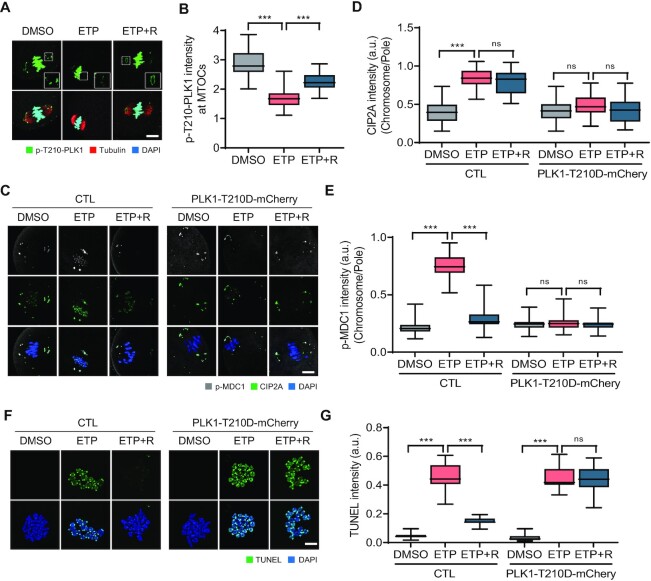
Figure 6.
DSB-induced PLK1 inactivation at spindle poles. (A) Representative images of oocytes showing localization of p-T210-PLK1 after ETP treatment and recovery (ETP + R). Scale bar, 10 μm. (B) Quantification of p-T210-PLK1 intensity at MTOCs. Data are presented as the mean ± SEM from three independent experiments. ***P < 0.0001. (C) Representative images showing p-MDC1 and CIP2A signals in oocytes expressing either mCherry or PLK1-T210D-mCherry. Scale bar, 10 μm. (D, E) Ratio of CIP2A and p-MDC1 intensities at chromosomes over spindle poles. Data are presented as the mean ± SEM from three independent experiments. ***P < 0.0001. ns, not significant. (F) Representative images of chromosome spreads showing TUNEL signals in oocytes expressing either mCherry or PLK1-T210D-mCherry. Scale bar, 10 μm. (G) Quantification of TUNEL intensity. Data are presented as the mean ± SEM from three independent experiments. ***P < 0.0001. ns, not significant.

