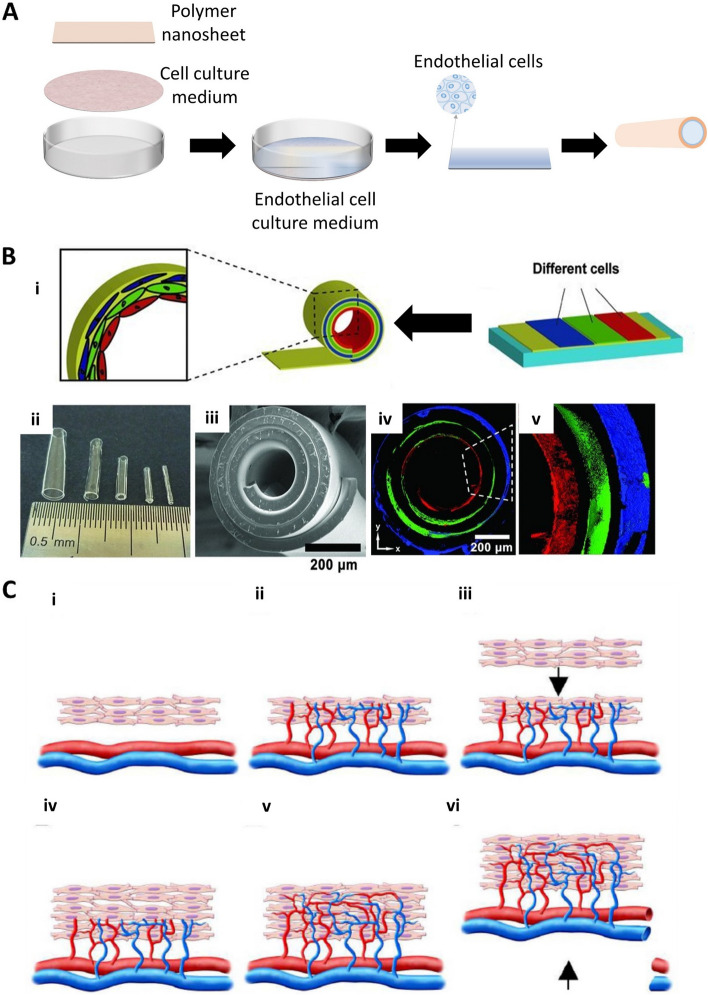
Fig. 7.
(A) Fundamental schematic diagrams of cell sheet engineering. (B) i) schematic illustrations of different cell delivery and the fabrication process of tissue-engineered vascular grafts. ii) Optical image of tubes with different diameters. The sizes of tubes are related to the thickness and stress of the membrane. iii) Scanning electron microscopy (SEM) images of a stress-induced rolling membrane with about three-layered walls. iv) Confocal images of the stress-induced rolling membrane with different cell distributions. Each color indicates a different type of cell. Red are endothelial cells (HUVECs); green: are smooth muscle cells; blue: are fibroblasts (NIH 3T3). Reproduced with permission [86]. Copyright 2012, John Wiley and Sons. (C) Schematic illustration of the concept used for bioengineering multilayer grafts with surgically connectable vessels. i) First graft is transplanted over a surgically accessible artery and vein. ii) The graft is supplied with new vasculature and blood directly from these existing vessels. iii, iv) After sufficient vascularization, the second graft is transplanted onto the first. v, vi) Finally, the micro-vascularized construct accompanied by available vessels harvested from the host is fully perfused by host vessels and surgically resected. Ectopic transplantation of such a graft is then possible. Reproduced with permission [111]. Copyright 2006, John Wiley and Sons

