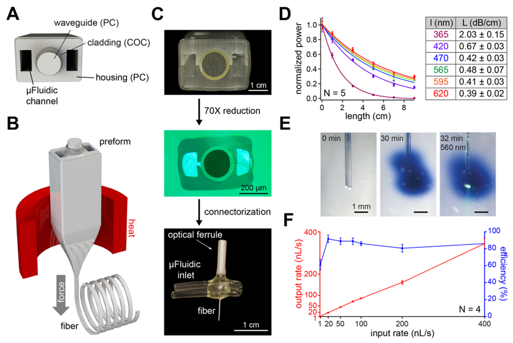
Figure 2.

Design and fabrication of a multifunctional fiber-based implant by thermal drawing. (A) Cross-section schematic of implants with two microfluidic channels and optical waveguide. (B) Schematic representing the thermal drawing process. (C) Cross-section of the preforms before thermal drawing (top). Cross-section of fibers after thermal drawing (middle). Fully connectorized device (bottom). (D) Optical loss calculation of the PC/COC optical waveguide across the visible spectrum (N = 5). (E) Injection of Trypan blue dye (2 μL over 30 min) into a phantom brain (0.6% agarose gel). 565 nm LED irradiation emerges from the device tip. (F) Output rate and efficiency following injection of 9 μL of water into a phantom brain using the microfluidic channel of 1 cm long multifunctional fiber-based neural implant (N = 4). Error bars = mean ± SEM.
