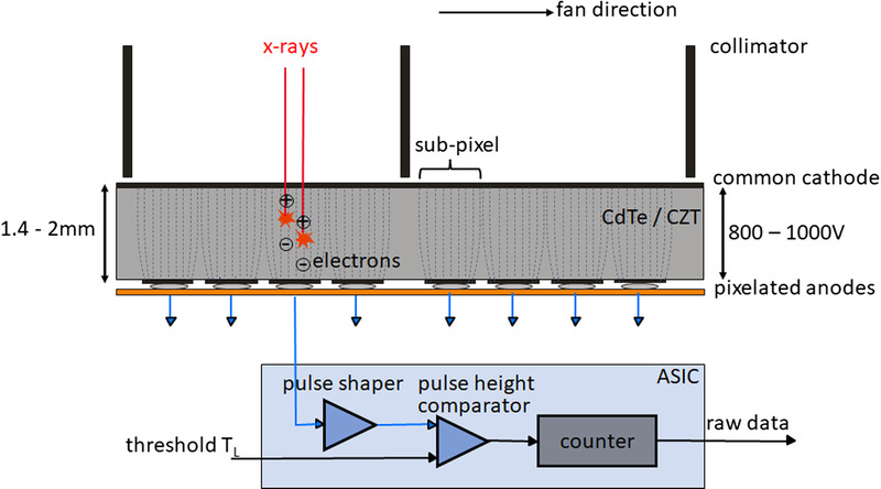
FIGURE 1.

Schematic illustration of a CdTe/CZT PCD (top) and the corresponding read-out ASIC (bottom). View from the front of the CT system, the fan direction is the direction in the scan plane along the detector fan. The individual detector pixels are formed by the strong electric field between the common cathode and the pixelated anodes (indicated here by dashed lines); no further separation of the pixels, for example, by interlayers, is necessary. In the detector structure shown here, 4 subpixels each are located between 2 collimator blades to suppress scattered radiation, see also Figure 4. In the ASIC, the voltage pulses generated by the absorbed x-ray quanta are compared in a pulse height comparator with a threshold voltage corresponding to the desired threshold energy (20–25 keV). Only x-ray quanta exceeding this threshold energy are counted.
