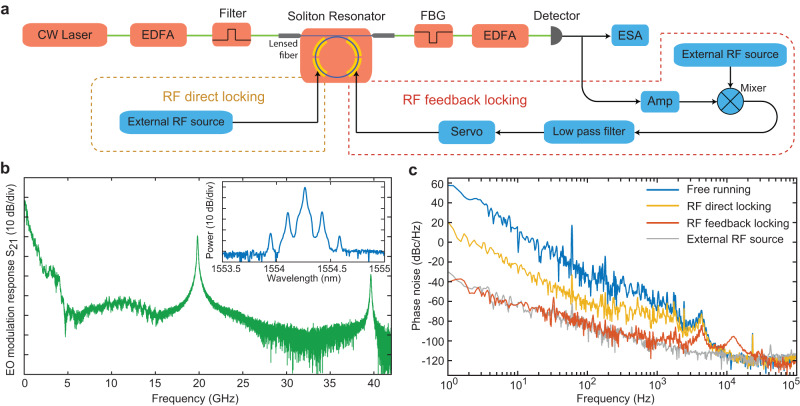
Fig. 4. Locking of soliton repetition rate to a reference microwave source.
a Schematic of the experimental testing setup. EDFA erbium-doped fiber amplifier, FBG fiber Bragg grating filter, Amp electrical amplifier. The soliton repetition rate is locked to an external reference microwave source (Anritsu, MG3697C) via two separate approaches. In the first approach, the external microwave signal directly drives the comb resonator at a modulation rate close to the resonator FSR (yellow dashed box). This is labeled as RF direct locking. In the second approach, the detected soliton microwave signal is compared with the external reference microwave, and the error signal is used to electro-optically tune the soliton repetition rate (red dashed box). This is labeled as RF feedback locking. b Electro-optic modulation response S21 of the comb resonator over a broad frequency range. The inset shows the optical spectrum of the produced comb-like sidebands when the comb resonator was driven with a 19.81 GHz microwave signal with a power of 20 dBm. The S21 curve was recorded at a low laser power such that the device functions as a pure electro-optic resonator, similar to Fig. 3a. c Phase noise spectrum of the detected 19.81 GHz microwave. The yellow and red curves show the case of RF direct locking (yellow box in a) and RF feedback locking (red box in a), respectively, while the blue curve shows the case when the device is free running. The gray curve shows the phase noise of the external reference microwave.

