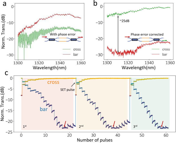
Fig. 6. Random phase error correction in a balanced MZI based on the multilevel operation.
a Transmission spectrum of a balanced MZI with phase error due to fabrication imperfections. The red (green) line represents bar (cross) transmission. Light transmits mostly from the bar port instead of the ideal cross port. b Transmission spectrum after the correction with 8.8 V, 150 ns, 232 nJ pulses. The device is in a “cross state” with a high extinction ratio of ~24 dB, indicating a phase-error-free device. c Time trace measurement for three experiments shows the phase error correction step. The RESET pulses are sent at a one-second interval. As more pulses were sent in, the bar transmission continuously decreased until it reached a minimum of ~−24 dB (red arrow), and then it went up. In all the experiments, the optimal error correction was obtained. The slight volatile increase (only visible when transmission is <−12 dB) after each amorphization pulse happens over a much longer timescale than 10 µs thermal relaxation time and could be attributed to a weak persistent photocurrent effect and requires more study. However, the transmission stabilizes before the next pulse. The blue (orange) represents bar- (cross-) transmission.

