Abstract
89Anatomic models have an important role in the medical domain. However, soft tissue mechanical properties’ representation is limited in mass-produced and 3D-printed models. In this study, a multi-material 3D printer was used to print a human liver model featuring tuned mechanical and radiological properties, with the goal of comparing the printed model with its printing material and real liver tissue. The main target was mechanical realism, while radiological similarity was a secondary objective. Materials and internal structure were selected such that the printed model would resemble liver tissue in terms of tensile properties. The model was printed at 33% scaling and 40% gyroid infill with a soft silicone rubber, and silicone oil as a filler fluid. After printing, the liver model underwent CT scanning. Since the shape of the liver is incompatible with tensile testing, tensile testing specimens were also printed. Three replicates were printed with the same internal structure as the liver model and three more out of silicone rubber with 100% rectilinear infill to allow a comparison. All specimens were tested in a four-step cyclic loading test protocol to compare elastic moduli and dissipated energy ratios. The fluid-filled and full-silicone specimens had initial elastic moduli of 0.26 MPa and 0.37 MPa, respectively, and featured dissipated energy ratios of 0.140, 0.167, 0.183, and 0.118, 0.093, 0.081, respectively, in the second, third, and fourth loading cycles. The liver model showed 225 ± 30 Hounsfield units (HU) in CT, which is closer to real human liver (70 ± 30 HU) than the printing silicone (340 ± 50 HU). Results suggest that the liver model became more realistic in terms of mechanical and radiological properties with the proposed printing approach as opposed to printing only with silicone rubber. Thus, it has been demonstrated that this printing method enables new customization opportunities in the field of anatomic models.
Keywords: Anatomic model, Additive manufacturing, Liver, Silicone, 3D printing
1. Introduction
90Anatomic models have subtle but important roles in medical technology and healthcare. In medical education, they facilitate lecturing and hands-on training in a risk-free way[1,2]. In medical device development, they accelerate progress and decrease costs by enabling repeatable testing and reducing animal or cadaver use[3]. In complex surgical cases, they aid preoperative planning and intraoperative orientation, which reduce operation time and likelihood of errors, improving overall patient safety[4,5]. Furthermore, anatomic models can facilitate progress in other fields, such as vehicle safety[6] or forensic medicine[7]. Thus, the overall improvement of anatomic models bears a considerable social impact.
Traditionally, anatomic models are mass-produced, commercial products where hard tissue models are made of hard plastics via injection molding, while soft tissue models use rubbers via casting[8-10]. Such models are widely used in medical education and device development due to their low price and availability, even though they come with three distinct limitations. The first one is that these mass-produced models do not match the anatomy of any specific patient, rendering them impractical for preoperative planning. This problem is eased by various 3D printing technologies that became mainstream over the past decade[11]. They enable the reproduction of patient anatomy, based on 3D geometry data segmented from medical images[12,13].
The second limitation is the representation of soft tissue mechanical properties, which affects all domain of anatomic model use cases. Neither mass-produced nor 3D-printed anatomic models capture the viscoelastic soft tissue behavior, which determines the forces arising from tool-tissue interaction or manual tissue handling during surgery[14]. Even though certain commercial technologies can print with various rubbers[15-20], their soft tissue model use cases are targeted at simply providing patient-specific geometries with an elastic material[21]. To ease the approximation of soft tissues using rubbers, Estermann et al.[22] compared various cast and 3D-printed rubber materials with fresh porcine and bovine liver tissues, pointing out that none of the discussed rubbers mimic the liver tissues from both an elastic and a viscous standpoint simultaneously. Meanwhile, according to a review by Witowski et al.[23], most reported 3D-printed liver models only target geometric accuracy and use hard materials. Ratinam et al.[24] reviewed various 3D-printed tissue mimicking options and suggested that soft tissues could be represented better if viscous liquids were included in 3D-printed structures. Further research efforts have addressed this problem of soft tissue representation in anatomic models, by either using commercial printers in innovative ways[25-28], or experimenting with self-built prototype printers[29-33]. However, none of these have experimented with combining different 3D printing technologies to improve soft tissue anatomic model realism.
Finally, the third limitation is a lack of anatomic models that mimic tissues in their appearance under various medical imaging modalities, while also retaining realistic mechanical properties[34]. Taking advantage of 3D printing to create image-based (thus potentially patient-specific) geometries, with materials and structures that mimic tissues from both a radiological and mechanical standpoint, is therefore a potential—albeit complex—way to improve anatomic model realism. Moreover, ample available data and the challenging mechanical properties of liver tissue[22,35,36] make it an ideal target for such investigations and test prints.
In recent publications, a custom-built prototype printer[37] was described that combines fused filament fabrication (FFF) and direct ink writing (DIW) technologies. The capabilities of this system in terms of printable geometries[38] have also been explored.
In this study, the complete design and manufacturing process of a mechanically and radiologically tuned liver model is presented. The goal of the study was twofold. The first goal was to develop a liver model that mimics real liver tissue concerning the initial elastic modulus and the dissipated energy ratio of the multi-material structure, while also considering printing limitations. The second goal was to compare the printed liver model in terms of mechanical and radiological properties with actual liver tissue as reported in literature. Finally, a reflection is provided on the potential uses, limitations, and development opportunities of the used printing technology in the domain of anatomic models.
2. Materials and methods
To achieve the goals of this study, a liver model and a set of tensile testing specimens have been designed and manufactured. The tensile testing specimens were necessary since the organic shape of the liver model is problematic in case of tensile testing. The liver model then underwent computed tomography (CT) scanning to reveal its radiological properties, while the tensile testing specimens were cyclically tested to evaluate the mechanical properties. Figure 1 provides an overview of what has been done in this study.
Figure 1.
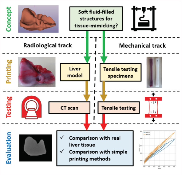
A summary of design, manufacturing, and evaluation steps performed in present study.
2.1. Segmentation and postprocessing
To obtain the geometry of a human liver, its shape was segmented from an anonymous torso CT scan, using the 91region growing segmentation tool of the open-source 3D-Slicer v5.0.3 software[39]. After exported from 3D-Slicer in STL format, the 3D data were postprocessed in Autodesk Meshmixer v3.5[40]. The main goal of the postprocessing was to smoothen the effects of the rather coarse CT scan resolution, and to repair any mesh errors stemming from exporting.
2.2. Design and materials
The primary objective in selecting materials and material structure for the liver model was achieving a degree of macroscopic mechanical realism. Realizing an anatomically correct internal organ structure was not in the scope of this study. In previous studies[36,35], fresh human, porcine and bovine liver tissue samples were found to exhibit strain-stiffening and viscoelastic tensile behavior. These studies suggest that for a liver-mimicking anatomic model, a material structure with an initial elastic modulus of approx. About 100 kPa should be used, after which some degree of strain-stiffening and viscoelastic behavior should be exhibited.
This is challenging, as all the previously tested single-component printing silicones are an order of magnitude stiffer according to their technical datasheets[38]. However, prior printing experience with the system[37,38] suggests that lower infill structures can make printed objects macroscopically softer than the bulk printing material, but printing infill structures below 40% silicone volume fraction is often unreliable in terms of printing success. 92Furthermore, preliminary experience of printing a viscous fluid into an infill structure has shown to increase viscous macroscopic mechanical behavior upon deformation.
Considering these limitations, a 40% gyroid infill volume fraction was chosen for the liver model, which would be filled with a viscous but inert filler fluid. This material structure is not expected to perfectly mimic the mechanical properties of human liver due to technological limitations, but to offer a more realistic—albeit still printable—alternative to printing or casting solely out of silicone rubber, while getting as close to the target elastic modulus (100 kPa) as possible with the printer and the known single-component printing materials.
The material chosen to print the shell and infill structure of the liver model was the softest available single-component liquid silicone rubber already tested with the system[38], namely the Elkem AMSil 20101 (Elkem Silicones SAS, Lyon, France)[41]. This material starts curing upon contact with air, with skin formation within 10 min and full crosslinking within 24 h after deposition at room temperature.
The rest of the internal space was filled up with a red-colored poly-dimethyl-siloxane (PDMS) oil with 100 Pa·s dynamic viscosity (Optimal Products GmbH, Bad Oeynhausen, Germany)[42]. This was chosen as the highest viscosity fluid available at the supplier that could still be filled into a cartridge to feed the printhead. Preliminary experience also showed that the presence of PDMS oil does not inhibit the crosslinking of the chosen silicone, as long as they are not mixed together. Dark red color was chosen to improve visual appearance and was achieved by mixing 1 w/w% of Silc Pig “Blood” paint (Smooth-On Inc., Macungie, PE)[43] with PDMS oil. It was assumed that this coloring additive does not have a significant effect on the overall mechanical behavior of the PDMS oil.
It was also expected that the liver geometry will require some degree of hard overhang support during printing. A common poly-lactic-acid (PLA) filament was selected (Material4Print GmbH & co. KG, Löhne, Germany) for printing the required support structure. The properties of all used materials are summarized in Table 1.
Table 1. Properties of the materials used to print the liver model.
| Material property | Silicone rubber (structure) | PDMS oil (filler fluid) | PLA (support) |
|---|---|---|---|
| Color | Translucent | Red | Black |
| Density (g/cm3) | 1.01 | 1.00 | 1.24 |
| Viscosity (Pa·s) | 410 | 100 | N/A |
| Shore hardness | A 18 | N/A | Approximately D 70 |
| Tensile strength (MPa) | 1.10 | N/A | 60 |
| Elongation at break (%) | 400 | N/A | 160 |
| Printing temperature (°C) | Room temperature | Room temperature | 200 |
| Shear thinning / shape holding | Yes | No | N/A |
| Pot life | Approximately 10 min | Inf. | N/A |
| Cure time | Approximately 24 h | Inf. | N/A |
2.3. Print settings and slicing
The print setup, slicing and G-code generation was conducted in the open-source Prusa Slicer v2.4.2[44] software (Figure 2). The liver model size was linearly downscaled to 33% in all three directions, so that printing the whole object would be possible with a single 55-mL cartridge of each material and within a working day. This downscaled STL file represented the outer shape of the liver model. Due to the organic and often overhanging shape, a relatively thick contour was desired to ensure sufficient sealing against filler fluid leakages, requiring an approximately 2-mm thick solid shell around the infill structure. To achieve this, the downscaled STL of the outer shape was further offset by 2 mm inwards in Meshmixer to represent the shape of the inner structure of the liver model (Figure 2A), occupied by both the infill structure and the filler fluid.
Figure 2.
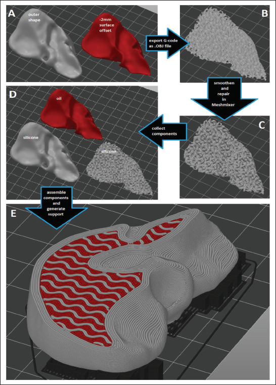
The workflow of generating the material structure in Prusa Slicer, involving (A) offsetting the outer shape, (B) slicing into the desired infill structure and exporting G-code pathways as an .OBJ file, (C) repairing and smoothening in Meshmixer, (D) re-importing all necessary components in Prusa Slicer, (E) assembling the liver model and generating support.
93To enable filling the infill structure with a fluid, the infill structure was generated and sliced first, then the resulting G-code pathways were exported as an OBJ file from Prusa Slicer (Figure 2B). This gyroid geometry was then smoothened in Meshmixer (Figure 2C), saved as a standalone STL file and reimported into Prusa Slicer (Figure 2D). Finally, this gyroid infill geometry was overlaid with the original outer shape as a multi-part (and multi-material) object, allowing the assignment of the silicone rubber nozzle to the outer shell and the gyroid pattern, and the PDMS oil nozzle to the cavities within the gyroid infill (Figure 2E). Support structures were generated 94 under the overhanging features of the liver model, and the FFF-nozzle (loaded with PLA filament) was assigned to all support structures (Figure 2E).
Since the liver model’s organic shape is incompatible with standard tensile testing protocols, the ASTM D638-14 Type I[45] tensile testing specimen geometry was printed three times with 7-mm thickness, approximately 1-mm solid shell (Table 2) and the same internal structuring as in the liver model to enable tensile testing and reveal how the liver model would behave if it could be tested. Additionally, three more tensile testing specimens were printed with 100% rectilinear infill out of silicone, to enable a comparison between the chosen fluid-filled gyroid structuring and the raw silicone material (Figure 3). The liver-matching tensile testing specimens were given a shell thickness of only 1 mm (as opposed to 2 mm in case of the liver model) to improve the quality and relevance of the tensile testing results. Preliminary experience showed that choosing a thinner shell may cause leakages of the filler fluid, while choosing a thicker shell would severely influence tensile testing results. Finally, a printing speed of 20 mm/s was selected for all seven print runs. A summary of the most important print settings is provided in Table 2.
Table 2. Key print settings of the liver model and tensile testing specimens.
| Setting | Value | Unit |
|---|---|---|
| Extrusion width | 0.5 | mm |
| Layer thickness | 0.3 | mm |
| Infill volume fraction (liver model and equivalent tensile specimens) | 40 | % |
| Infill volume fraction (full-silicone tensile specimens) | 100 | % |
| Infill type (liver model and equivalent tensile specimens) | Gyroid | |
| Infill type (full-silicone tensile specimens) | Rectilinear | |
| Contour (liver model) | 4 | lines |
| Contour (all tensile testing specimens) | 2 | lines |
| Solid top and bottom (liver model) | 6 | layers |
| Solid top and bottom (all tensile testing specimens) | 3 | layers |
| Print speed | 20 | mm/s |
| Travel speed | 50 | mm/s |
| Travel and tool change Z-lift | 1 | mm |
| Acceleration | 500 | mm/s2 |
Figure 3.
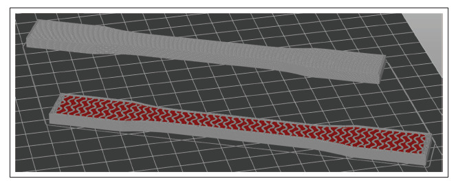
Tensile testing specimens after slicing in Prusa Slicer, with a liver-matching specimen (bottom) and a full-silicone benchmark specimen (top) displayed with the top layers hidden, to compare the inside of the specimens.
2.4. Printer calibration and printing
The printer used in this study is an open-source FFF machine that was modified to accommodate a dual fluid extruder while retaining its original FFF printhead. It is described in more technical detail in refs.[37] and [38]. The two halves of the fluid extruder are operable independently. One was filled with the liquid silicone rubber, the other with the red-colored high-viscosity PDMS oil, both fed from air-pressurized 55-cm3 cartridges at 6 bars. The PLA filament was loaded into the original FFF printhead of the printer. All three extruders used nozzles with 0.4-mm inner diameter. This resulted in an approximately 0.5-mm extrusion width for each nozzle, while the layer thickness was 0.3 mm in general. Both fluid extruder halves were calibrated to their respective material along the calibration process described in ref.[38] to ensure accurate dosing. After extruder calibration, the liver model (Figure 4A), three tensile testing specimens matching the liver model’s internal structure (Figure 4B) and three silicone-only benchmark specimens were printed. All printing was conducted in ambient conditions, at room temperature. The objects were left to crosslink for approximately 48 h at room temperature after printing. After removal from the building platform and removal of PLA support structures in case of the liver model, the objects were weighed on a KERN EMB 200-3 laboratory scale (Kern&Sohn GmbH, Balingen, Germany) to ensure that none of them has a relative weight error larger than ±5%.
Figure 4.
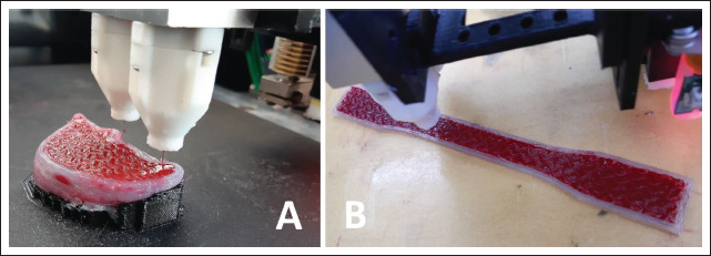
(A) Printing the liver model. (B) Printing a tensile testing specimen.
2.5. Mechanical testing
The tensile testing specimens underwent a cyclical quasistatic uniaxial tensile testing protocol. The test setup involved a ZwickRoell Z030 tensile testing machine (Zwick Roell GmbH, Ulm, Germany) operating at 10 Hz sampling frequency and a Sony α-6400 high-resolution camera (Sony, Tokyo, Japan) at 1 Hz frame frequency (Figure 5A). White dot markers were placed onto the specimens for deformation tracking (Figure 5B) as also described in[46,47]. Effective gauge length (defined by the dot markers) was approximately 72 mm for all specimens.
Figure 5.
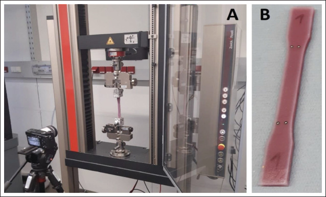
(A) The tensile testing setup. (B) The marker placement on a tensile testing specimen.
The test protocol started with a preload of 5 mm, and involved four consecutive loading cycles, with 7.5%, 15%, 22.5%, and 30% target strains, respectively, providing information not only about stiffness, but also about viscous behavior. All cycles were performed at 0.1 mm/s displacement rate. Deformation values were obtained via digital image correlation (DIC) as explained in further detail in[46]. During DIC, the marker positions were tracked, and the relative displacement between them was calculated. Afterward, the engineering strain (ε) was computed according to Equation I:
| (I) |
where L0 is the initial distance between markers (at preload only) and L is the actual distance between markers at a given sampling moment based on DIC results, while A0 95is the initial cross-sectional area, measured with a caliper before testing.
Meanwhile, the uniaxial linear engineering stress (σ) was calculated using Equation II:
| (II) |
where f is the measured axial force and A0 is the initial cross-sectional area.
The ratio of dissipated energy over a loading-unloading cycle was taken a measure of the overall viscous behavior of the multi-material structure. The total energy of a loading cycle is the area under the stress–strain curve of the loading half-cycle, while the dissipated energy of a loading cycle is the area within the hysteresis loop formed by the stress–strain curves of loading and unloading half-cycles[48]. The dimensionless ratio of the dissipated energy to the total energy is referred to as the dissipated energy ratio. Besides plotting the stress–strain curves of all four loading-unloading cycles and the initial and final elastic moduli on the last loading cycle, the dissipated energy ratios for the second, third, and fourth cycles were also calculated. In this regard, the first loading cycle was ignored due to distortions coming from the preload.
2.6. Imaging
Due to the lack of respective data on fluid-filled structures and the fact that the chosen design logic of the liver model did not allow for deliberate tuning for radiological properties, achieving a degree of imaging realism was only an option but nevertheless a preferred outcome. Therefore, the liver model underwent CT scanning (SOMATOM Definition AS, Siemens Healthineers, Erlangen Germany) with a modified clinical CT protocol to evaluate the radiodensity properties. The CT scan settings are listed in Table 3.96
Table 3. Key CT settings used on the liver model.
| Setting | Value | Unit |
|---|---|---|
| Tube voltage | 120 | kVp |
| Tube current time product (with tube current modulation) | 80 | mAs |
| Slice thickness | 0.60 | mm |
| Pixel size | 0.29 | mm |
| Pitch | 0.55 | - |
The table height was set to 120.5 mm and no surrounding material was used. For all sample scans, a smooth J30s reconstruction kernel was applied. Analyze 12.0 toolkit (AnalyzeDirect, Over-land Park, KS) was used to estimate the average Hounsfield unit (HU) values of the liver model. Various line profiles were manually selected inside the internal structure of liver model, and the overall HU was estimated by calculating the average and the standard deviation over all points along the selected line profiles. The same method was used on the solid silicone shell of the liver model, for comparison with the internal structure.
3. Results
3.1. Printing
The liver model and the tensile testing specimens were printed successfully (Figure 6), and all seven objects were found acceptable upon weighing. The liver model, the three matching tensile testing specimens, and the three full-silicone benchmark tensile testing specimens took approximately 10, 4, and 3 h of printing time apiece, respectively.
Figure 6.
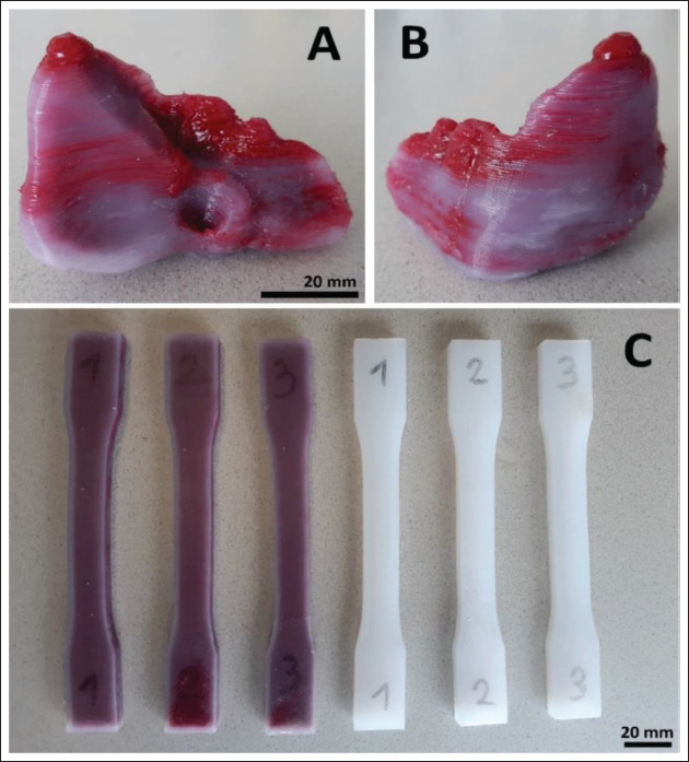
(A and B) The liver model after crosslinking and support removal. (C) The tensile testing specimens after crosslinking.
3.2. Mechanical and radiological properties
The tensile testing results showed a more elastic and more viscous behavior in case of the fluid-filled tensile testing specimens compared to the full-silicone benchmark specimens (Figure 7A–C). In the last loading cycle, the average initial elastic moduli (calculated between 0% and 3% strain) of the fluid-filled structure and the full silicone were 0.26 MPa and 0.37 MPa, respectively, while the final moduli (calculated between 22% and 27% strain) were 0.19 MPa and 0.25 MPa, respectively (Figure 7D). The average dissipated energy ratios were higher and increasing across loading cycles in case of the fluid-filled structure, while lower and decreasing across loading cycles in case of full silicone. The first loading cycle was ignored in this regard due to the preload.
Figure 7.
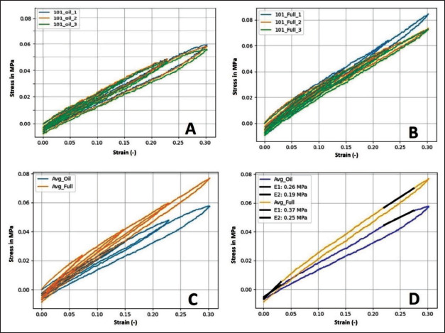
(A) Tensile behavior of the individual fluid-filled specimens over all four loading cycles. (B) Tensile behavior of the individual full silicone specimens. (C) Average tensile behavior of the fluid-filled tensile testing specimens compared to the full silicone ones. (D) Comparison in average behavior over the last loading cycle only, also with comparison between the initial (E1 between 0% and 3% strain) and final (E2 between 22% and 27% strain) tensile moduli.
Finally, the CT scan showed an average HU density and standard deviation of 225 ± 30 HU for the internal structure of the liver model, excluding its solid shell (Figure 8). Meanwhile, the pixels of the solid shell showed an HU of 340 ± 50, suggesting that the liver model became more realistic due to the internal structuring compared to the 97bulk silicone (Table 4). A summary of the elastic moduli, dissipated energy ratios and HUs is given in Table 4, along with liver tissue values for comparison.
Figure 8.
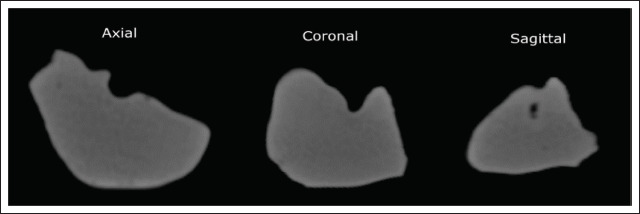
Appearance of the liver model in the CT scan in all three planes. Each view was sectioned approximately at the middle of the respective envelope dimension of the model.
Table 4. Average elastic moduli, dissipated energy ratios and Hounsfield units.
| Liver model and fluid-filled specimens (n = 1 + 3) | Full silicone specimens (n = 3) | Liver tissue (based on[35,36,49,50]) | |
|---|---|---|---|
| Initial elastic modulus (kPa) (E1 on Figure 7, at 0%–3% strain) | 260 | 370 | Approximately 100 (target in this study) |
| Final elastic modulus (kPa) (E2 on Figure 7, at 22%–27% strain) | 190 | 250 | N/A |
| Dissipated energy ratio (–) of first loading cycle (0%–7.5% strain) | N/A | N/A | Approximately 0.6 ± 0.1 |
| Dissipated energy ratio (–) of second loading cycle (0%–15% strain) | 0.140 | 0.118 | |
| Dissipated energy ratio (–) of third loading cycle (0%–22.5% strain) | 0.167 | 0.093 | |
| Dissipated energy ratio (–) of fourth loading cycle (0%–30% strain) | 0.183 | 0.081 | |
| HU of fluid-filled internal structure of liver model | 225 ± 30 | N/A | Approximately 70 ± 30 |
| HU of bulk outer shell of liver model | 340 ± 50 | N/A |
4. Discussion
In this study, a liver model was designed based on a CT-image regarding its shape and available literature regarding its desired mechanical properties, while accounting for technological limitations. The infill pattern generation workflow relies on open-source software, which may be useful for other researchers for filling infill structures with fluids. A previously published and tested open-source printer[37,38] was used to manufacture the liver model and a set of tensile testing specimens out of silicone rubber and 98 99PDMS oil, using PLA as support. The printed liver model underwent CT scanning, and it was found that its internal structuring has brought it closer to actual liver tissue HUs compared to the bulk silicone material. Meanwhile the tensile testing results show that the used internal structure has also brought the liver model closer to real liver tissue from a mechanical standpoint compared to bulk silicone, decreasing elastic moduli and increasing dissipated energy ratios.
4.1. Printing performance and limitations
Despite the extensive use of PLA support structures, the liver model presented a relatively straightforward print run. The visible color inhomogeneities (Figure 6A and B) were likely caused by unwanted droplets of the filler fluid falling onto the object from the inactive nozzle. This could be avoided either with longer pullback settings upon tool switching, or by upgrading the printer with a tool-changing or lifting mechanism for inactive extruders, as described in refs.[18] and [19].
Theoretically, the liver model could also be printed without downscaling to 33% in each direction, but a full-scale model would consume large amounts of material, and require frequent cartridge changes, and either a printing time over a week, or a much coarser printing resolution with larger nozzle. In such a case, some anatomical features—like larger and medium-sized vessels—could also be represented inside the internal structure of the liver model, but at a cost of potentially compromising freedom in mechanical and radiological property tuning.
Moreover, in case of larger prints with soft materials, the deformation of the printed object under its own weight would likely require some degree of compensation, and such a feature is not yet available in current 3D printing software. Alternatively, printing could happen in a support bath with the same density as the printing materials, which would prevent a large soft object from such deformations. However, this would also prevent the use of any closed internal cavities or filler fluids. In general, solving such practical limitations of the printer were not in the scope of this study, since the demonstration of material property tuning was possible.
4.2. Mechanical behavior and limitations
In case of the fluid-filled structure, the lower elastic moduli (compared to full silicone) are likely caused by having less silicone in the internal structure (Figure 8), while the increase in dissipated energy ratios (Table 4) can be associated with the viscous filler fluid circulating within the silicone gyroid structure upon deformation.
As stated in section 2.2 and Table 4, the desired initial elastic modulus was 100 kPa, after which some degree of strain-stiffening and overall viscoelastic behavior was desired. As expected with the knowledge of printing limitations, the fluid-filled tensile testing specimens (and thus, the liver model) provided a mechanical behavior that is closer to real liver tissue than the behavior of the full silicone benchmark specimens, in terms of both elasticity and viscosity, although not matching it perfectly with an initial elastic modulus of 260 kPa instead of 100 kPa, and dissipated energy ratios in the range of 0.14–0.19, instead of approx. 0.5–0.7 (Table 4).
The elastic modulus could have been even lower with a softer material or if the specimens were printable with no solid outer shell. Unfortunately, the latter is not possible by principle, as the fluid would leak from the specimens upon deformation if there was no shell.
Also, the typical strain-stiffening behavior characteristic to liver tissue[35] was not reflected in the results in this study. This is not surprising, since most biological tissues feature a fibrous hierarchic structure, which stiffens when 100strained. Such fibers were not present in the current internal structuring strategy, suggesting further potential topics for future trials. In general, conducting future trials with multiple levels of design parameters and various materials—as in ref. [49] or [50]—may reveal further material combinations that are especially useful in tissue mimicking.
Comparison of the present liver model with others in literature is difficult, as most clinical studies involving printed liver models do not report the exact material properties of the printing materials according to systematic reviews on the topic by Witowski et al. and Qiu et al.[21,23]. However, most reported liver models rely on FFF or stereolithography technologies with hard materials and focus on geometry only. The ones that use droplet jetting (PolyJet) also focus on geometry and use transparent but relatively hard materials (Vero) instead of softer ones (TangoPlus), which could theoretically enable some degree of mechanical tissue mimicking[21].
4.3. Radiological behavior and limitations
The comparability between the obtained CT scan of the liver model and scans of real human liver tissue in literature is somewhat limited due to numerous differences in CT systems, energy settings, surrounding materials, orientation, and postprocessing methods. However, such a comparison of HUs may help evaluate the results at least from a qualitative standpoint.
The HU values of the human liver are approximately 70 ± 30 HU[51,52] within a typical general CT value range of approximately −1000 (air) to +1000 (cortical bone) HU. Meanwhile, an average 225 ± 30 HU was observed in the internal structure of the liver model. Printing the model out of pure silicone rubber would have yielded a higher, 340 ± 50 average HU for the inside of the model as well, not only for the outer shell. Moreover, it is known from prior experiments[53] that a gyroid infill structure of 40% with single-component silicones (without filler fluid) yields approximately −500 HU.
Therefore, the chosen fluid-filled internal structuring has made the model more realistic from a radiological standpoint compared to both the bulk silicone material and the same infill structure without fluid filling. Furthermore, the radiological appearance of such fluid-filled internal structures may be further altered by using various filler fluid mixtures to reach a wider range of HUs[34], considering a potential future direction of research.
5. Conclusion
In this study, a custom-built multi-material 3D printer was used to print a downscaled liver model out of silicone rubber and PDMS oil, using PLA for support structures. The chosen fluid-filled internal structure has brought the model closer to actual liver tissue from both a mechanical and a radiological standpoint at the same time compared to both bulk silicone and matching but fluid-free infill structuring. These results prove that extrusion-based multi-material fluid printing represents a versatile platform for tissue approximation in terms of both mechanical and radiological properties in functional anatomic models. Meanwhile, hardware, software, and material constraints that limited tissue mimicking accuracy in the case of the present liver model were identified, and respective upgrades or improvements were proposed. Once such improvements are made, the present printing and material structuring method could significantly contribute to the current state of the art in realistic anatomic models, offering an extrusion-based alternative to droplet jetting and an open-source alternative to commercial systems at the same time.
Acknowledgments
None.
Funding
This work was supported by the Provincial Government of Lower Austria (Land Niederösterreich) under grant assignment number WST3-F2-528983/005-2018.
Conflict of interest
Concerning the 3D-printing technology used in this work, a patent application has been filed at the European Patent Office under applicant reference number 51241 by the Austrian Center for Medical Innovation and Technology (ACMIT Gmbh). The inventors of this pending application are Laszlo Jaksa, Andrea Lorenz and Dieter H. Pahr.
Author contributions
Conceptualization: Laszlo Jaksa, Andrea Lorenz, Dieter H. Pahr, Gernot Kronreif
Formal analysis: Laszlo Jaksa, Othniel James Aryeetey, Sepideh Hatamikia
Funding acquisition: Dieter H. Pahr, Gernot Kronreif
Investigation: Laszlo Jaksa, Katharina Nägl, Martin Buschmann
Methodology: Laszlo Jaksa, Othniel James Aryeetey, Sepideh Hatamikia
Project administration: Andrea Lorenz
Supervision: Dieter H. Pahr, Andrea Lorenz
Writing – original draft: Laszlo Jaksa
Writing – review and editing: All authors
Ethics approval and consent to participate
101Not applicable.
Consent for publication
Not applicable.
Availability of data
Not applicable.
References
- 1.Preece D, Williams SB, Lam R, et al. Let’s get physical: Advantages of a physical model over 3D computer models and textbooks in learning imaging anatomy. Anat Sci Educ. 2013;6(4):216–224. doi: 10.1002/ase.1345. https://doi.org/10.1002/ase.1345. [DOI] [PubMed] [Google Scholar]
- 2.Khot Z, Quinlan K, Norman GR, et al. 2013. The relative effectiveness of computer-based and traditional resources for education in anatomy Anat Sci Educ 64 211-215 https://doi.org/10.1002/ase.1355 [DOI] [PubMed] [Google Scholar]
- 3.Wang K, Ho CC, Zhang C, et al. A review on the 3D printing of functional structures for medical phantoms and regenerated tissue and organ applications. Engineering. 2017;3(5):653–662. https://doi.org/10.1016/J.ENG.2017.05.013. [Google Scholar]
- 4.Pugliese L, Marconi S, Negrello E, et al. 2018. The clinical use of 3D printing in surgery Updates Surg 703 381-388 https://doi.org/10.1007/s13304-018-0586-5 [DOI] [PubMed] [Google Scholar]
- 5.Tack P, Victor J, Gemmel P, et al. 3D printing techniques in a medical setting: A systematic literature review. Biomed Eng Online. 2016;15(115) doi: 10.1186/s12938-016-0236-4. https://doi.org/10.1186/s12938-016-0236-4. [DOI] [PMC free article] [PubMed] [Google Scholar]
- 6.Mohan P, Marzougui D, Kan CD. Development and validation of hybrid III crash test dummy. SAE Technical Paper. 2009 https://doi.org/10.4271/2009-01-0473. [Google Scholar]
- 7.Humphrey C, Kumaratilake J. Ballistics and anatomical modelling—A review. Leg Med. 2016;23(12):21–29. doi: 10.1016/j.legalmed.2016.09.002. https://doi.org/10.1016/j.legalmed.2016.09.002. [DOI] [PubMed] [Google Scholar]
- 8.Trehan K, Kemp CD, Yang SC. 2014. Simulation in cardiothoracic surgical training: Where do we stand? JTCS 1471 18 24 https://doi.org/10.1016/j.jtcvs.2013.09.007 [DOI] [PubMed] [Google Scholar]
- 9.Kurt E, Yurdakul SE, Atac A. 2013. An overview of the technologies used for anatomy education in terms of medical history Proc Soc 103 109 115. https://doi.org/10.1016/j.sbspro.2013.10.314 [Google Scholar]
- 10.Cooper JB, Taqueti VR. 2004. A brief history of the development of mannequin simulators for clinical education and training Qual Saf Health Care 13:563 115 https://doi.org/10.1136/qshc.2004.009886 [DOI] [PMC free article] [PubMed] [Google Scholar]
- 11.Ngo TD, Kashani A, Imbalzano G, et al. Additive manufacturing (3D printing): A review of materials, methods, applications and challenges. Compos B Eng. 2018;143172-196:172–115. https://doi.org/10.1016/j.compositesb.2018.02.012. [Google Scholar]
- 12.Nikitichev DI, Patel P, Avery J, et al. 2018. Chapter 6: Patient-specific 3D printed models for education, research and surgical simulation in 3D Printing IntechOpen Limited; London, United Kingdom: https://doi.org/10.5772/intechopen.79667 [Google Scholar]
- 13.Waran V, Narayanan V, Karuppiah R, et al. Injecting realism in surgical training-initial simulation experience with custom 3D models. J Surg Educ. 2014;71193(2) doi: 10.1016/j.jsurg.2013.08.010. https://doi.org/10.1016/j.jsurg.2013.08.010. [DOI] [PubMed] [Google Scholar]
- 14.Wang K, Wu C, Qian Z, et al. 2016. Dual-material 3D printed metamaterials with tunable mechanical properties for patient-specific tissue-mimicking phantoms Addit Manuf 12:31 115. https://doi.org/10.1016/j.addma.2016.06.006 [Google Scholar]
- 15.Yeo J, Koh J, Wang F, et al. (eds.), 2020. Chapter 9: 3D printing silicone materials and devices in Silicon Containing Hybrid Copolymers John Wiley & Sons Inc; https://doi.org/10.1002/9783527823499.ch9 [Google Scholar]
- 16.Spectroplast AG https://spectroplast.com/, viewed 04.08.2022. [Google Scholar]
- 17.Stratasys Ltd https://stratasys.com/medical/advanced-medical-models, viewed 04.08.2022. [Google Scholar]
- 18.Deltatower GmbH https://deltatower.ch/en/home-2/, viewed 04.08.2022. [Google Scholar]
- 19.CR-3D www.cr3d.de/3d-drucker/liquid-serie/, viewed 02.11.2022. [Google Scholar]
- 20.Lynxter SAS lynxter.fr/en/product/3d-printing-silicone-toolhead-liq21/, viewed 02.11.2022. [Google Scholar]
- 21.Qiu K, Haghiashtiani G, McAlpine MC. 3D printed organ models for surgical applications. Annu Rev Anal Chem. 2018;11(1):287–306. doi: 10.1146/annurev-anchem-061417-125935. https://doi.org/10.1146/annurev-anchem-061417-125935. [DOI] [PMC free article] [PubMed] [Google Scholar]
- 22.Estermann SJ, Pahr DH, Reisinger A. Quantifying tactile properties of liver tissue, silicone elastomers, and a 3D printed polymer for manufacturing realistic organ models. Mech Behav Biomed Mater. 2020;104:103630. doi: 10.1016/j.jmbbm.2020.103630. https://doi.org/10.1016/j.jmbbm.2020.103630. [DOI] [PubMed] [Google Scholar]
- 23.102Witowski JS, ColesBlack J, Zuzak TZ, et al. 3D Printing in liver surgery: A systematic review. Telemed e-Health. 2017;23(12):943–947. doi: 10.1089/tmj.2017.0049. https://doi.org/10.1089/tmj.2017.0049. [DOI] [PubMed] [Google Scholar]
- 24.Ratinam R, Quayle M, Crock J, et al. Challenges in creating dissectible anatomical 3D prints for surgical teaching. J Anat. 2019;234(4):419–437. doi: 10.1111/joa.12934. https://doi.org/10.1111/joa.12934. [DOI] [PMC free article] [PubMed] [Google Scholar]
- 25.Truby RL, Lewis JA. Printing soft matter in three dimensions. Nature. 2016;540(7633):371–378. doi: 10.1038/nature21003. https://doi.org/10.1038/nature21003. [DOI] [PubMed] [Google Scholar]
- 26.Ionita CN, Mokin M, Varble N, et al. Challenges and limitations of patient-specific vascular phantom fabrication using 3D Polyjet printing. Proc SPIE Int Soc Opt Eng. 2014;9038:90380M. doi: 10.1117/12.2042266. https://doi.org/10.1117/12.2042266. [DOI] [PMC free article] [PubMed] [Google Scholar]
- 27.Maddox MM, Feibus A, Liu J, et al. 3D-printed soft-tissue physical models of renal malignancies for individualized surgical simulation: A feasibility study. J Robot Surg. 2018;12(1):27–33. doi: 10.1007/s11701-017-0680-6. https://doi.org/10.1007/s11701-017-0680-6. [DOI] [PubMed] [Google Scholar]
- 28.Saari M, Xia B, Krueger PS, et al. Additive manufacturing of soft and composite parts from thermoplastic elastomers. Proceedings of the International Solid Freeform Fabrication Symposium, 2015 Austin, TX. [Google Scholar]
- 29.Bakarich SE, Gorkin R, Panhuis M, et al. Three-dimensional printing fiber reinforced hydrogel composites. ACS App Mater Interfaces. 2014;6(18):15998–16006. doi: 10.1021/am503878d. https://doi.org/10.1021/am503878d. [DOI] [PubMed] [Google Scholar]
- 30.Hardin JO, Ober TJ, Valentine AD, et al. Microfluidic printheads for multimaterial 3D printing of viscoelastic inks. Adv Mater. 2015;27(21):3279–3284. doi: 10.1002/adma.201500222. https://doi.org/10.1002/adma.201500222. [DOI] [PubMed] [Google Scholar]
- 31.Jung JW, Lee JS, Cho DW. 2016. Computer-aided multiple-head 3D printing system for printing of heterogeneous organ/tissue constructs Sci Rep 6:21685 https://doi.org/10.1038/srep21685 [DOI] [PMC free article] [PubMed] [Google Scholar]
- 32.Liu W, Zhang YS, Heinrich MA, et al. Rapid continuous multimaterial extrusion bioprinting. Adv Mater. 2016;29(3):1604630. doi: 10.1002/adma.201604630. https://doi.org/10.1002/adma.201604630. [DOI] [PMC free article] [PubMed] [Google Scholar]
- 33.SkylarScott MA, Mueller J, Visser CW, et al. Voxelated soft material via multimaterial multinozzle 3D printing. Nature. 2019;575(7782):330–335. doi: 10.1038/s41586-019-1736-8. https://doi.org/10.1038/s41586-019-1736-8. [DOI] [PubMed] [Google Scholar]
- 34.Talalwa L, Natour G, Bauer A, et al. Radiological characteristics of a new experimental rubber elastomeric polymer used in three-dimensional printing with different infill densities and patterns. J Phys Commun. 2020;4(12):125006. https://doi.org/10.1088/2399-6528/abd1c3. [Google Scholar]
- 35.Estermann SJ, FörsterStreffleur S, Hirtler L, et al. Comparison of thiel preserved, fresh human, and animal liver tissue in terms of mechanical properties. Ann Anat. 2021;236:151717. doi: 10.1016/j.aanat.2021.151717. https://doi.org/10.1016/j.aanat.2021.151717. [DOI] [PubMed] [Google Scholar]
- 36.Estermann SJ, Pahr DH, Reisinger A. 2020. Hyperelastic and viscoelastic characterization of hepatic tissue under uniaxial tension in time and frequency domain Mech Behav Biomed Mater 112:104038 https://doi.org/10.1016/j.jmbbm.2020.104038 [DOI] [PubMed] [Google Scholar]
- 37.Jaksa L, Pahr DH, Kronreif G, et al. Development of a multi-material 3D printer for functional anatomic models. Int J Bioprint. 2021;7(4) doi: 10.18063/ijb.v7i4.420. https://doi.org/10.18063/ijb.v7i4.420. [DOI] [PMC free article] [PubMed] [Google Scholar]
- 38.Jaksa L, Pahr DH, Kronreif G, et al. Calibration dependencies and accuracy assessment of a silicone rubber 3D printer. Inventions. 2022;7(35) https://doi.org/10.3390/inventions7020035. [Google Scholar]
- 39.3D-Slicer https://www.slicer.org/, viewed 04.08.2022. [Google Scholar]
- 40.Autodesk Meshmixer https://www.meshmixer.com/, viewed 04.08.2022. [Google Scholar]
- 41.Elkem AMSil Silicones https://www.elkem.com/silicones/brands/amsil/, viewed 04.08.2022. [Google Scholar]
- 42.Optimal Products GmbH https://optimal-products.de/silikonoele/, viewed 04.08.2022. [Google Scholar]
- 43.Smooth-On Silc Pig Paints https://www.smooth-on.com/products/silc-pig/, viewed 04.08.2022. [Google Scholar]
- 44.Prusa Research a.s. https://www.prusa3d.com/page/prusaslicer_424/, viewed 04.08.2022. [Google Scholar]
- 45.ASTM D638-14 viewed August 04, 2022 https://www.astm.org/d0638-14.html https://www.astm.org/d0638-14.html, viewed 04.08.2022. [Google Scholar]
- 46.Aryeetey OJ, Frank M, Lorenz A, et al. A parameter reduced adaptive quasi-linear viscoelastic model for soft biological tissue in uniaxial tension. Mech Behav Biomed Mater. 2021;126:104999. doi: 10.1016/j.jmbbm.2021.104999. https://doi.org/10.1016/j.jmbbm.2021.104999. [DOI] [PubMed] [Google Scholar]
- 47.Frank M, Marx D, Nedelkovski V, et al. Dehydration of individual bovine trabeculae causes transition from 103ductile to quasi brittle failure mode. Mech Behav Biomed Mater. 2018;87:296–115. doi: 10.1016/j.jmbbm.2018.07.039. https://doi.org/10.1016/j.jmbbm.2018.07.039. [DOI] [PubMed] [Google Scholar]
- 48.Aryeetey OJ, Frank M, Lorenz A, et al. Fracture toughness determination of porcine muscle tissue based on AQLV model derived viscous dissipated energy. Mech Behav Biomed Mater. 2022;153:105429. doi: 10.1016/j.jmbbm.2022.105429. https://doi.org/10.1016/j.jmbbm.2022.105429. [DOI] [PubMed] [Google Scholar]
- 49.Goh GD, Sing SL, Lim YF, et al. Machine learning for 3D printed multi-materials tissue-mimicking anatomical models. Mater Des. 2021;211:110125. https://doi.org/10.1016/j.matdes.2021.110125. [Google Scholar]
- 50.Kwon J, Ock J, Kim N. Mimicking the mechanical properties of aortic tissue with pattern-embedded 3D printing for a realistic phantom. Materials. 2020;13(21):5042. doi: 10.3390/ma13215042. https://doi.org/10.3390/ma13215042. [DOI] [PMC free article] [PubMed] [Google Scholar]
- 51.Rietzel E, Schardt D, Haberer T. Range accuracy in carbon ion treatment planning based on CT-calibration with real tissue samples. Radiat Oncol. 2007;2(14) doi: 10.1186/1748-717X-2-14. https://doi.org/10.1186/1748-717X-2-14. [DOI] [PMC free article] [PubMed] [Google Scholar]
- 52.Toledo JM, Ribeiro TPC. Radiological evaluation of a liver simulator in comparison to a human real liver. Proceedings of the International Nuclear Atlantic Conference - INAC. 2009 2009. ISBN: 978-85-99141-03-8. [Google Scholar]
- 53.Jaksa L, Hatamikia S, Pahr DH, et al. 3D-printer enabling customized anatomic models, Poster at the 27th Congress of the European Society of Biomechanics, Porto, Portugal. 2022 https://doi.org/10.13140/RG.2.2.28812.39049. [Google Scholar]
Associated Data
This section collects any data citations, data availability statements, or supplementary materials included in this article.
Data Availability Statement
Not applicable.


