Fig. 1.

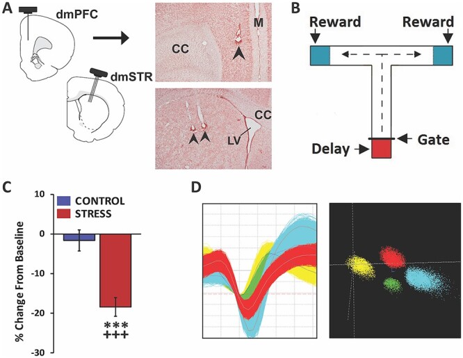
Experimental approach. A) Schematic depicting 8-wire recording ensembles simultaneously targeting layer V of the dmPFC and the dmSTR. Accurate placement was confirmed in stained tissue sections. Photomicrograph of a coronal section demonstrating recording sites in dmPFC (top panel) and dmSTR (bottom panel). Arrows indicate recording electrodes tip location. CC, corpus collosum; LV, lateral ventricle; M, midline. B) Schematic of the delayed-response T-maze testing apparatus. Between trials, the animal is held in the start box (red shading) for a delay interval. Animal exit during the delay is prevented by a removeable gate. At the end of a successful trial the animal receives a reward (blue shading) before it is picked up and placed back in the start box. C) Animals were connected to a headstage and recorded for a baseline testing session in the morning and, in the afternoon, either a no-stress control session or noise-stress testing session. The headstage remained connected across morning and afternoon testing sessions. When tested under no-stress control conditions (control), working memory performance accuracy did not differ significantly from baseline. In contrast, stress significantly impaired performance, relative to baseline and no-stress controls. D) Left: action potential waveforms of 4 discriminated WS dmPFC neurons from a single wire. Right: waveforms from these units exhibit separable clusters in 3D-principal component space. Analyses ensured the same neurons were recorded across baseline and stress or no-stress testing sessions. ***P < 0.001 vs. no-stress controls; +++P < 0.001 vs. baseline.
