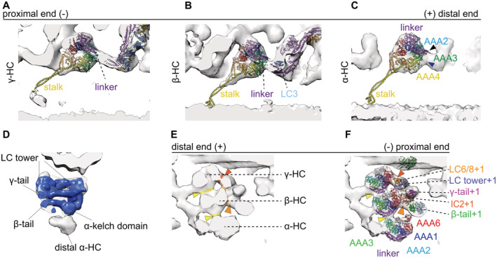
Figure 7. Intermediate conformation.

-
A–CSurface render maps of the γ (A) β (B) α HC (C) are shown with the cytoplasmic pre‐PS dynein PDB‐4RH7 (Schmidt et al, 2015) rigid body fitted. The tail complex from PBD‐7MOQ is fitted as a rigid body. The bend linker of the PDB structure is in agreement with the γ‐ (A) and β‐HC (B). For α‐HC (C), the linker (purple) does adapt an intermediate conformation, whereas the linker spans over AAA3 (bottom blue arrowhead) instead of going over AAA2 (top black arrowhead).
-
DThere are no major deviations between the tail structure of the postmodel and the intermediate conformation tomographic map.
-
EThe intra‐ODA connection between the β‐head and theγ‐linker is highlighted in yellow. The inter‐ODA connections of the β‐dynein head to the IC2 and the connection of the γ head to the LC tower are indicated in orange.
-
FPDB structures fitted to the same view as in (E), highlighting which proteins are involved in the tail‐to‐head interactions. The highlighted regions from I are marked with arrows in E. The linker of the γ and β‐HC is interacting with the AAA3 of the β and α HC, respectively (yellow arrows). AAA6 of the γ‐HC interacts with the proximal LC tower (red arrow). The AAA6 of the β‐HC interacts with the IC2 of the proximal ODA (light orange arrow).
