



Abstract
Guidewire technology has advanced significantly over the last several decades. As more components are incorporated providing valuable features, deciding which guidewire to use during peripheral artery disease (PAD) interventions has become more complex. The challenge for both the beginner and expert is not only understanding which components offer the best characteristics in a guidewire but choosing the optimal wire for an intervention. Manufacturers have attempted to optimize components to provide physicians with routinely available guidewires needed in everyday practice. Yet selecting the best guidewire for a particular situation during an intervention is still challenging. This article provides a basic overview of guidewire components and what benefits they offer during PAD interventions.
Keywords: guidewire components, guidewire features, core, spring coils, covers, coating, tip design, tip load, tip penetrance, interventional radiology
The understanding of guidewire characteristics is crucial in the treatment of peripheral arterial disease (PAD). Vascular physicians commonly prefer a set of specific guidewires and typically have a personal wire escalation strategy to treat patients. Guidewires are utilized for access, navigation, crossing of a stenosis or chronic total occlusion (CTO), and to deliver treatment. Given the array of available guidewires on the market, learning guidewire technology and choosing the optimal guidewire can be challenging. The choice of guidewire, however, can make the difference between an unsuccessful and a successful revascularization. While there are a myriad of guidewire features, this article will focus on major guidewire components and give an introduction of how guidewires are typically categorized.
Core, Coils/Covers, Coating, Tip Design
In general, guidewire performance is determined by several key features: core, coils/covers, coating, and tip design 1 2 ( Fig. 1 ).
Fig. 1.

Key guidewire elements. (Adapted from image provided courtesy of Boston Scientific. © 2022 Boston Scientific Corporation or its affiliates. All rights reserved.)
Core
Core Material
Guidewire core components include core material, core diameter, and core taper. The core material may be composed of nitinol, stainless steel, or a hybrid of the two. Nitinol wires provide excellent kink resistance, flexibility, shape retention, and durability, but they have less support for delivery of devices and are more difficult to shape. Stainless steel wires have excellent pushability, torqueability, and rail support, but they are less flexible and kink resistant and more easily damaged. A hybrid wire is sometimes created to include all of the aforementioned features by using a stainless-steel core and a nitinol tip. 1 2 3
Core Diameter
Core diameter allows for variable guidewire sizes including 0.014, 0.018, and 0.035 inch in diameter. Smaller diameters allow for increased flexibility and are ideal for crossing high-grade stenoses. Larger diameters provide more rail support and tend to straighten tortuous vessels to allow for optimal delivery of devices for treatment.
Core Taper
The core taper of a wire is the transition from the core diameter to the start of the tip of a guidewire. Gradual or long tapers are better for accessing a branch arising at an acute angle from the parent vessel and allow the wire to follow without prolapsing out of the branch. Guidewires with abrupt or short tapers tend to have better support over short distances and prolapse easily which is helpful during a subintimal recanalization but not for selecting branches arising at acute angles from the parent vessel 1 2 3 ( Fig. 2 ).
Fig. 2.

Long taper versus short taper guidewires. Long tapers aid in selecting and tracking into a branch vessel arising at an acute angle. Short taper wires have better support over short distances and prolapse easily, which is helpful during a subintimal recanalization but not for selecting branch vessels arising at an acute angle. (Image provided courtesy of Boston Scientific. © 2022 Boston Scientific Corporation or its affiliates. All rights reserved.)
Coils and Covers
Spring coils wrapped around the distal wire allow for greater support with shorter lengths and greater flexibility with longer lengths. They also result in tip resiliency and more tactile feel but more friction due to resistance from their grooves. To reduce this friction, a cover or sleeve known as a polymer jacket consisting of polyurethane is often placed over the spring coil to smooth out these grooves resulting in less friction and thus increased lubricity which helps with CTO crossability and device deliverability 2 3 ( Figs. 3 and 4 ).
Fig. 3.
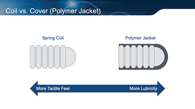
The spring coil design provides more tip resilience and tactile feel but more friction due to its grooves. A polymer jacket placed over a spring coil smooths out the grooves, which reduces friction and provides more lubricity thereby improving CTO crossability and device deliverability. (Image provided courtesy of Boston Scientific. © 2022 Boston Scientific Corporation or its affiliates. All rights reserved.)
Fig. 4.

Electron micrography images showing how a polymer jacket over a spring coil smooths out its grooves. (Image provided courtesy of Boston Scientific. © 2022 Boston Scientific Corporation or its affiliates. All rights reserved.)
Coating
Coatings are also used in addition to covers to make guidewires more hydrophilic or hydrophobic. Hydrophilic coatings bond with water to create a slippery gel increasing lubricity which promotes crossability and trackability but reduces tactile feel. Guidewires with hydrophobic coatings are “water repelling” and therefore less lubricious. The advantage is more tactile feel but with increased resistance during advancement. Common examples of hydrophobic coatings include silicone and PTFE 1 2 3 ( Figs. 5 and 6 ).
Fig. 5.

Hydrophilic versus hydrophobic guidewire coatings. (Image provided courtesy of Boston Scientific. © 2022 Boston Scientific Corporation or its affiliates. All rights reserved.)
Fig. 6.

Hydrophilic coatings and polymer jackets both result in increased lubricity with less tactile feel, whereas hydrophobic coatings result in decreased lubricity but improved tactile feel. (Image provided courtesy of Boston Scientific. © 2022 Boston Scientific Corporation or its affiliates. All rights reserved.)
Tip Design
A guidewire's tip design includes many of the components described earlier including spring coils/covers, core taper, and coatings. Three additional important components are core length, tip load, and tip penetrance.
Core Length
When the core of the wire extends to the tip, there is improved transmission of force, durability, steerability, and tactile feedback making these types of guidewires ideal for PAD interventions. On the other hand, when the core of the wire does not extend to the tip, the guidewire tends to be softer, more flexible, shapeable, and less traumatic to arteries. This type of tip easily prolapses making it better for subintimal recanalization or navigating through stents.
Tip Load and Tip Penetrance
Tip load and tip penetrance are important guidewire features for CTO crossing. Tip load refers to the grams of axial pressure needed to deflect the distal 1 cm of a guidewire 2mm ( Fig. 7 ). Tip penetrance is determined by tip diameter and tip load. In general, guidewire tip penetrance increases as the tip diameter decreases and tip load increases ( Fig. 8 ). While increased tip load and tip penetrance help for CTO crossing, tactile feel is reduced and the risk of perforation is increased. 1 2 3 4
Fig. 7.

Guidewire tip load definition and how it is determined. (Adapted from image provided courtesy of Boston Scientific. © 2022 Boston Scientific Corporation or its affiliates. All rights reserved.)
Fig. 8.

Guidewire tip penetrance increases as the tip diameter decreases and tip load increases. The higher the tip penetrance, the better a guidewire is at crossing a CTO but with increased risk of vessel perforation. (Image provided courtesy of Boston Scientific. © 2022 Boston Scientific Corporation or its affiliates. All rights reserved.)
Guidewire Categories
Understanding guidewire components and how they determine and change the features of wires is a complex and important topic. However, despite understanding their components, determining which guidewire to use during a PAD intervention is not always easy. Most vascular experts rely on what they learned from their mentors and during their training, endovascular courses, talking to colleagues, and on the job experience to determine personal guidewire escalation strategies. Companies who manufacture guidewires try to help physicians by choosing a specific combination of guidewire components to create a wire that can be used for different clinical situations ( Fig. 9 ). With this in mind, most companies categorize guidewires as navigational/workhorse/frontline, specialty/crossing/CTO, or supportive/delivery wires.
Fig. 9.

One example of choosing guidewire features based on CTO cap type, degree of calcification, presence of collaterals for transcollateral crossing, and vessel tortuosity. (Adapted from image provided courtesy of Boston Scientific. © 2022 Boston Scientific Corporation or its affiliates. All rights reserved.)
Navigational/Workhorse/Frontline Guidewires
These wires are mainly used for access or traversing the arterial network of blood vessels to reach a stenosis, CTO, or the intended treatment area. They tend to have low tip loads with tips that are soft, flexible, shapeable, and prolapse easily.
Specialty/Crossing/CTO Guidewires
These wires are commonly used for crossing high-grade stenoses or CTOs. While they can still be flexible and shapeable, they tend to have higher tip loads and tip penetrance. Many also have hydrophilic coatings and tapered tips to improve their crossability features and help with finding microchannels for CTO crossing. Although higher tip load wires offer better CTO penetrance, the risk of arterial perforation or creating a subintimal channel is increased, both of which may make the CTO crossing more challenging.
Supportive/Delivery Wires
Once a stenosis or CTO is crossed, a supportive or delivery wire is used for treatment. These wires tend to have a soft atraumatic tip; so, they can be advanced distal to an area of intervention without causing vessel trauma. In addition, they often have a stainless steel core and a hydrophobic coating to maximize support.
Conclusion
The technology of guidewires and understanding how each component changes its features is complex. Understanding these guidewire components is crucial to choosing the best wire or wires during a PAD intervention. The ability to navigate, have tactile sense, steer, cross, deliver treatment, and avoid distal vessel injury is based on wire technology. If vascular physicians master guidewire components and understand their nuances, procedural success during PAD interventions will be improved.
Disclosures
M.P. has no disclosures. S.T. is a course faculty, speaker, and consultant for Abbott Vascular, Terumo Corp., Cardiovascular Systems Inc.
References
- 1.Walker C. Guidewire selection for peripheral vascular interventions: understanding the design elements of interventional guidewires is the basis for successful use. Endovascular Today 2013;(May):80–83
- 2.Fornell D. Understanding the Design and Function of Guidewire Technology. Diagnostic and Interventional Cardiology. October 12, 2016. Accessed April 5, 2023 at:
- 3.Dave B. Recanalization of chronic total occlusion lesions: a critical appraisal of current devices and techniques. J Clin Diagn Res. 2016;10(09):OE01–OE07. doi: 10.7860/JCDR/2016/21853.8396. [DOI] [PMC free article] [PubMed] [Google Scholar]
- 4.Mishra S. Language of CTO interventions - focus on hardware. Indian Heart J. 2016;68(04):450–463. doi: 10.1016/j.ihj.2016.06.015. [DOI] [PMC free article] [PubMed] [Google Scholar]