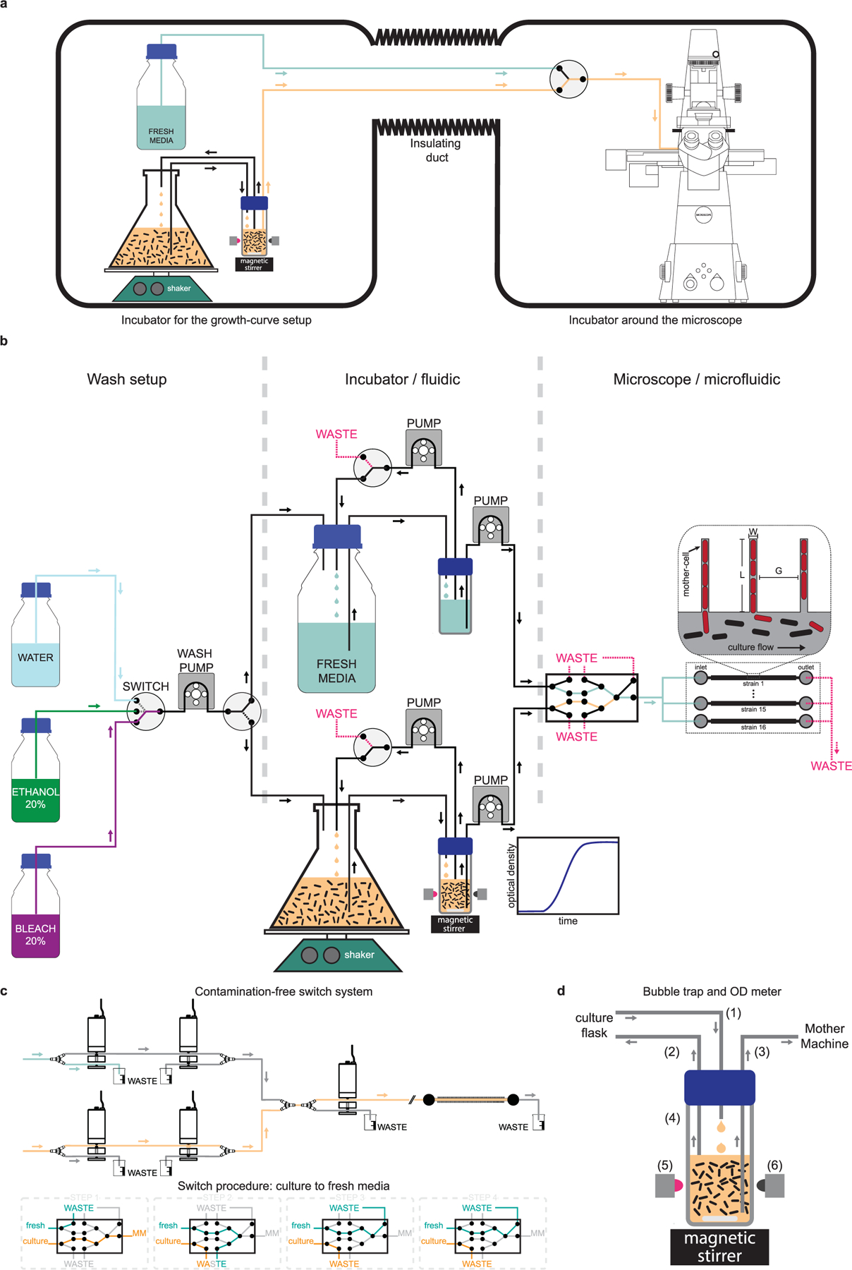
Extended Data Fig. 1 |. Operating principle of the single-cell growth-curve setup.

a, Schematic of the dual incubator setup is shown. The incubator in the left houses the growth curve setup (culture flask, shaker, and automated optical density measurement system), and the fresh media reservoir. The commercial incubator on the right houses the microscope and the microfluidic device in which cells are loaded. These two incubators are connected via an insulated duct through which the tubing that carry cells and media go from the flask to the microfluidic device. b, Detailed schematic of the flow-setup – showing the pumps, switches and liquid reservoirs. The box on the left shows the setup used for automatically washing the system before and after every run. A peristaltic pump and a 4-way switch are used to sequentially pump liquid from the reservoirs containing bleach, ethanol, and water to the culture flask or the media reservoir. The box in the center shows components that are housed in the incubator shown on the left of (a). Cells are grown in a baffled-bottom culture flask, which is placed on an orbital shaker. An inline automated OD-meter is used for continuously monitoring the optical density of the culture using a LED-photodiode pair. A set of pumps flow the culture to the OD meter and back, while another one flows it to the microfluidic device. A similar set of pumps are used on the path for fresh media, and both paths can be used interchangeably. The box on the right shows the components housed in the second incubator. These include a set of pinch valves that enable switch from culture to fresh media, and vice versa. We use five 3-way pinch-valves to make sure there is minimal delay in switch, the wash is clean and devoid of any residual bacteria from the culture, and the path is free of bubbles. This design also keeps individual paths isolated and enable wash with bleach, ethanol, and water, while the other path is in use. The media coming out of the final (rightmost) valve can be split using a manifold to flow through different flow-channels in the microfluidic device. d, A detailed schematic of the pinch valve assembly and sequences of steps involved in the media switch is shown. e, Schematic of the bubble-trap is shown to illustrate the principle of operation. Media from the culture flask is dripped into the reservoir (1) and a taken out using another tubing (2) that is placed at the liquid interface to remove bubbles and extra liquid. Due to this design, the media at the bottom of the reservoir stays essentially free of bubbles and is delivered to the mother-machine using a tubing (3) whose inlet is all the way at the bottom of the reservoir. The reservoir has transparent glass-walls (4) and the magnetic stirrer is used to prevent the culture from settling down and to keep it uniform. We use a LED (5) to shine near-IR light through the culture and monitor the transmittance using a photodiode (6) placed in the opposite direction to quantify the optical density of the culture.
