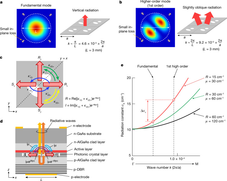
Fig. 1. Control of Hermitian and non-Hermitian optical couplings inside the photonic crystal to increase the threshold gain margin between the fundamental and higher-order modes.
a, Typical electric-field intensity distribution (left panel) and schematic of radiation (right panel) of the fundamental mode in a PCSEL with a diameter of L. b, Typical electric-field intensity distribution (left panel) and schematic of radiation (right panel) of a higher-order mode in the same PCSEL. The higher-order mode emits a multilobed beam in a slightly oblique direction. c, Hermitian couplings between the four fundamental waves (Rx, Sx, Ry and Sy) inside a PCSEL with a double-lattice photonic crystal. d, Schematic of the cross-sectional structure of the PCSEL and the non-Hermitian couplings between the fundamental waves via radiative waves inside the device, where the couplings between Rx and Sx are illustrated as an example. A backside reflector (p-type distributed Bragg reflector (p-DBR)) is used to control the magnitude of the non-Hermitian coupling coefficient. e, Calculated radiation constants of mode A as functions of k when the values of R and μ are changed.

