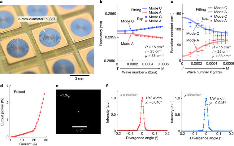
Fig. 2. Development of a 3-mm-diameter PCSEL and demonstration of very narrow beam divergence under pulsed operation.
a, Photograph of the fabricated 3-mm-diameter PCSEL chips. b,c, Frequencies (b) and radiation constants (c) as functions of k for modes A and C. The dots indicate experimental data (Exp.) obtained from the peak wavelengths and line widths of the spontaneous emission spectrum at each wave number. The solid lines are theoretical curves based on equation (1), where the best-fit results are R = 15 cm−1, I = 25 cm−1 and μ = 38 cm−1. The vertical error bars in b and c represent measurement uncertainty associated with the central frequency and the spectral line width, and the horizontal error bars represent measurement uncertainty associated with the wave number. d, Measured I–L characteristics under pulsed conditions. The pulse width and repetition frequency were set to 200 ns and 200 Hz, respectively. e, Measured FFP at an injection current of 1.3Ith. f, Cross-sectional intensity profiles of the FFP along the x and y directions. A very narrow 1/e2 divergence angle of 0.045° was obtained owing to the achievement of small yet appropriately balanced values of R and μ as described in the text. a.u., arbitrary unit.

