
FIGURE 1.
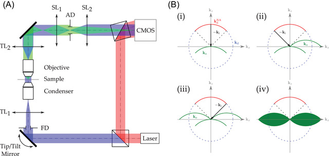
(A) Sketch of a typical DHM‐based TDM configuration. Red beam is associated with the reference wavefront, blue beam is the illumination wavefront and green beam is the wavefront diffracted by the investigated sample. and , respectively, denote the condenser and microscope objective tube lenses. The sampling doublet made of and lenses ensures adequate sampling of the interferograms. FD and AD are the Field Diaphragm and the Aperture Diaphragm, respectively. (B) Building of the 3D object potential from sequential hologram acquisitions (illustrated in 2D for convenience). Hologram spectrum registering according to Equation (1) for perpendicular illumination (i), at collection objective maximum NA (ii,iii), full 3D object potential (iv)