Figure 5.

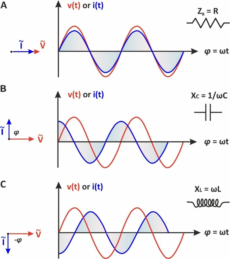
(Left) phasor diagrams and (right) the respective sinusoidal waveforms v(t) and i(t) when a low amplitude alternating voltage is applied to (A) a resistor, (B) a capacitor, and (C) an inductor.

(Left) phasor diagrams and (right) the respective sinusoidal waveforms v(t) and i(t) when a low amplitude alternating voltage is applied to (A) a resistor, (B) a capacitor, and (C) an inductor.