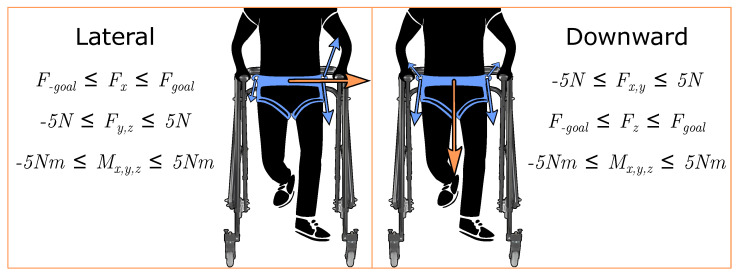
Figure 2.
Forces applied to the pelvis and their associated quadratic programming wrench constraints. Here, x refers to the mediolateral axis and z refers to the vertical axis. For the lateral force, is limited within a small range of N. All other forces and moments are limited within N or Nm. These ranges were selected to minimize forces in other directions while ensuring that the goal lateral and downward forces could be achieved by the mTPAD’s controller. Similarly for the downward force, is limited within N from . The orange arrows depict the frontal plane pelvic forces that are applied by the mTPAD. The blue arrows depict the cable tensions, with the relative size representing the relative tension required to apply the pelvic forces. These pelvic forces are synchronized with the user’s gait cycle percentage corresponding to single stance. All seven cables are actuated to minimize all other forces and moments.

