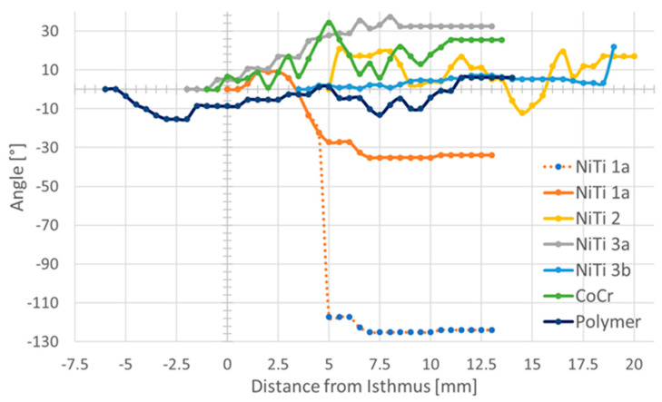
Figure 9.
Rotation of the longest axis of the stents. The first cross-section of the stent at the side facing the middle ear was taken as origin and angles were then always measured in relation to this first image. Zero on the x-axis refers to the isthmus for each ET. For stent NiTi 1a, the measured values (blue dots) and the 90° corrected values (solid line) are provided. Note that in the region with the perceived negative rotation, this stent was not unfolded.

