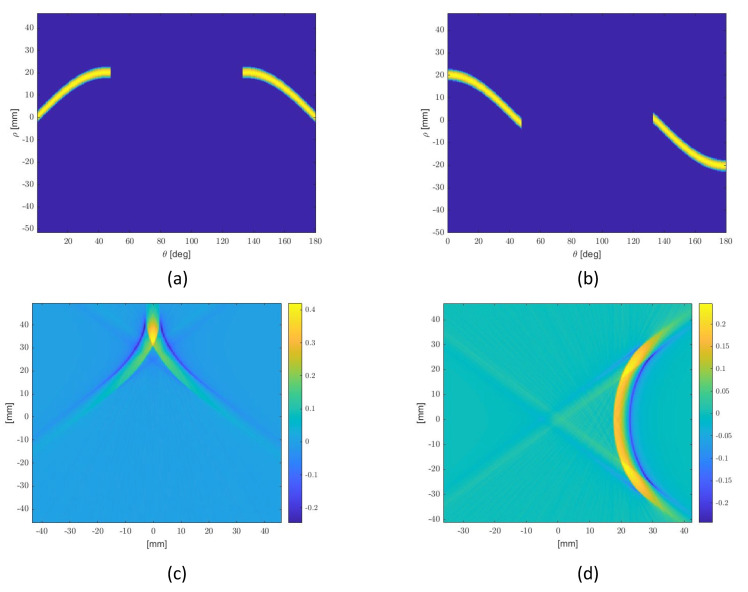
Figure 5.
A graphical illustration of the re-shaping design procedure. P2 and P3 are related to the first and second column respectively: (a,b) Imposed RTs, equal to disk one in [−45°, 45°], unless there are shifts in (according to the numerators of Equation (19)); (c,d) IRTs: ideal shape functions.

