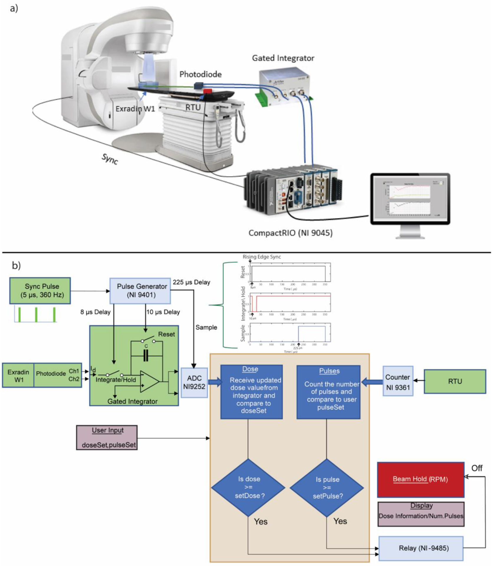
Figure 1.

a) Schematic of the hardware and signal routing for real-time beam monitoring. The beam monitoring hardware primarily consisted of a real-time controller, a gated integrator, a plastic scintillator, and a remote trigger unit. b) Shows the control algorithm consisting of redundant dose feedback based on pulse counting and dose accumulation. The signal routing is also depicted here along with the different I/O modules and radiation detectors. The pulse sequence realized via the hardware to integrate dose per pulse is also shown in b). Green colored boxes represent external signals from the linac and detectors, whereas the light blue boxes represent the I/O modules used in this study. The yellow box in the middle denotes the control algorithm used in this study. Boxes with light shade of red denote the information required from the user and displayed after dose delivery.
