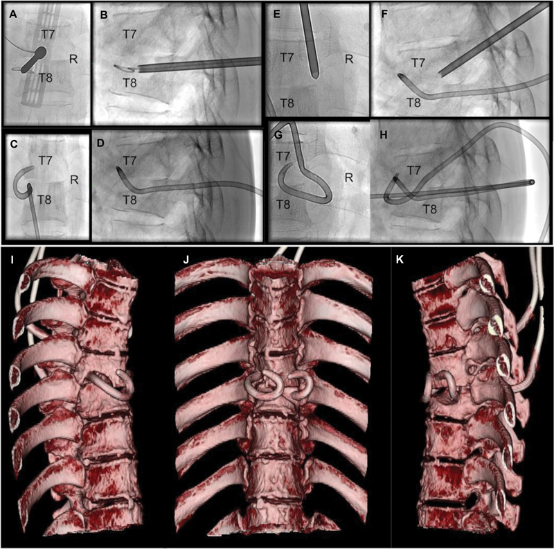
Fig. 3.

Intraoperative radiological images ( A–D : left transpedicular drainage, E–H : right transpedicular drainage). ( A ) An 8G bone marrow biopsy needle is set in the center of the left pedicle of T8. ( B ) A catheter is transpedicularly introduced through a guidewire. ( C, D ) A catheter is placed in the left paravertebral abscess cavity ( C , anterior posterior projection and D , lateral projection). ( E ): An 8G bone marrow biopsy needle is set in the cranial margin of the right pedicle of T7. ( F ) An 8G bone marrow biopsy needle was introduced in the direction of the inferior margin of the T7 vertebral body. ( G, H ) A catheter is placed in the right paravertebral abscess cavity ( G : anterior posterior projection, H : lateral projection). Postoperative three-dimensional reconstructed computed tomography images demonstrating the placement of bilateral drainage catheters in the paravertebral abscess cavity ( I–K ).
