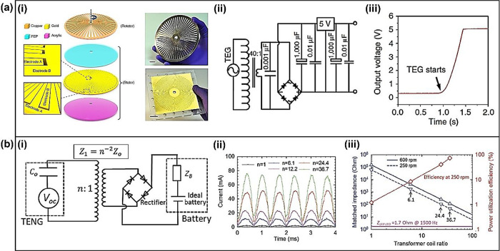
Figure 61.
Inductive transformer for TENG. (a)-(i) Schematic illustrations of the radial-arrayed rotary TENG. (a)-(ii) Circuit diagram of the complete power-supplying system that consists of a triboelectric generator and a power management circuit. (a)-(iii) Output voltage of the system reaches a constant value of 5 V in less than 0.5 s as the triboelectric generator starts to rotate at 3,000 r/min. Reprinted with permission from ref (555). Copyright 2014 Springer Nature. (b)-(i) The equivalent circuit of battery charging by the TENG with the aid of a transformer and a rectifier. (b)-(ii) Rectified currents of the TENG at the same rotating speed (250 rpm) but with different transformers (n = 1, 6, 12, 24, and 36). (b)-(iii) The effect of the transformer coil ratio on matched impedances of the TENG, and the power utilization efficiency of the TENG at 250 rpm when charging an LFP–LTO full cell. Reprinted with permission under a Creative Commons CC BY license from ref (558), Copyright 2015, John Wiley and Sons.

