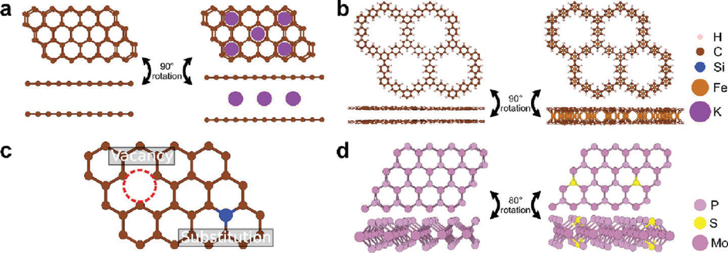
Figure 2.
Modeling intercalation, defects, and doping in 2D materials. (a) Bilayer graphene before (left) and after (right) intercalation. The figure includes a top view (top) and a side view (bottom). (b) “All-benzene” 2D-COF before (left) and after (right) intercalation. Intercalated atoms are placed at the centroid of each benzene ring. The figure includes a top view (top) and a side view (bottom). (c) Defective graphene layer showing a vacancy and a silicon substitution. (d) Pristine (left) and S-doped (right) MoP. The figure includes a top view (top) and a triclinic view (bottom).

