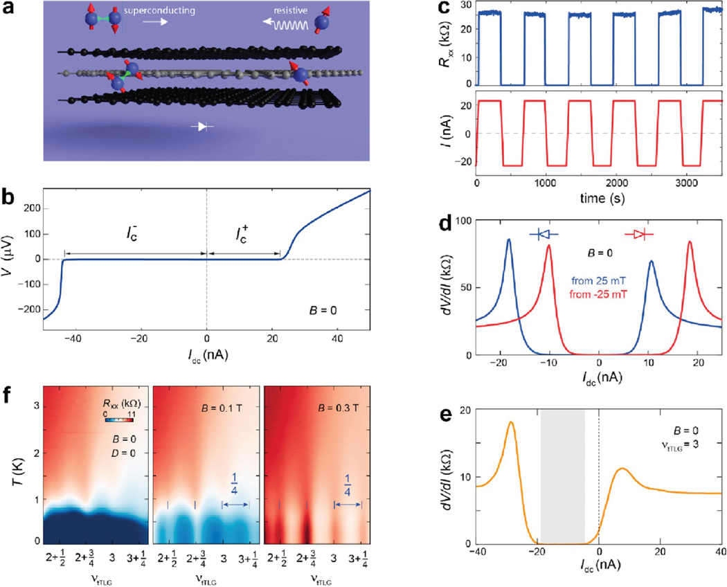
Figure 24.
Nonreciprocity and superconducting diode effect. (a) Schematic diagram showing the superconducting diode effect. Cooper pairing is only stable when current flows from left to right. As a result, the transport response across the sample is dissipationless when current flows from left to right, whereas a resistive behavior is observed when current direction is reversed. (b) Differential resistance as a function of DC current bias of the superconducting phase at and are the critical current with positive and negative DC current bias, respectively. The asymmetry in and shows the nonreciprocity. (c) Demonstration of robust zero-field superconducting diode effect. (d, e) Field-training of the superconducting diode: (d) After a positive (negative) field training, the superconducting diode remains as a reverse (forward) diode as shown in the blue (red) curve. (e) Extremely high diode efficiency at large doping, as the zero-resistance regime (shaded part) has shifted totally to the negative current side. (f) Interplay between superconductivity and density-wave state. Longitudinal resistance as a function of temperature and doping, at different magnetic fields. As the magnetic field increases, superconductivity is suppressed and density-wave state (resistance oscillations with 1/4 periodicity) takes over at the low temperature range. Adapted with permission from ref 440. Copyright 2022 Springer Nature.

