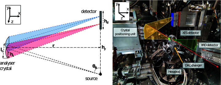
Figure 1.
(Left) Scheme of the von Hámos setup. The sample is a point source (black point) that emits at multiple energies, seen from the side for a horizontal scattering angle of 90° relative to the incoming X-ray beam. The detector plane at height h y has a perpendicular distance r to the cylindrically bent analyser crystal with a bending radius of r and an area of h c × l c. High-energy (blue) and low-energy (red) X-rays are diffracted with different Bragg angles θB and focused in the non-dispersive direction leading to a straight line signal in the dispersive direction (y) on the detector plane with the size h d. X-rays propagate along z through the emitting source point. (Right) The setup in IC1 includes a DAC exchanger and XRD detectors downstream of the sample. The X-ray beam (red), XES (yellow) and XRD (green) paths are shown. The XES detector array is marked in blue. Example figures of the detector images for different analyser crystal arrangements are shown in Fig. S2.

