Fig. 1.
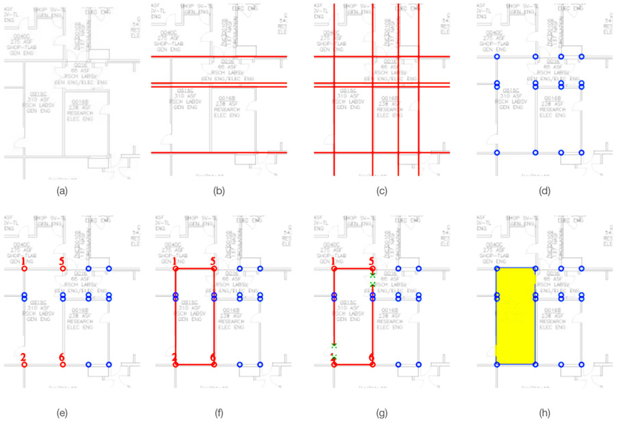
Tracing a map with SIM. (a) A portion of the floor plan. (b) Horizontal lines are generated via shift-clicks. (c) Vertical lines are generated next. (d) All line intersections (potential wall corner or endpoints) are automatically computed and displayed. (e) The user clicks on the appropriate line intersections that identify the boundary of a space (Room 310). These intersections are automatically assigned ID numbers. (f) The user then selects the walls surrounding the space by choosing the intersection pairs (#1, #5), (#5, #6), (#6, #2), (#2, #1). (g) The user defines one entrance in the wall segment (#1, #2) and one in the wall segment (#5, #6). (h) At this point, the space can be recorded and the user can move on to defining a new space.

