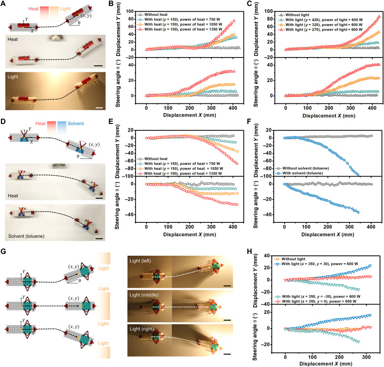
Fig. 4. Autonomous changes to trajectory in response to environmental inputs.
(A) The schematic and experimental images show that the robot can autonomously steer its trajectory closer to light or heat. (B) The trajectories (displacement and steering angle) of the robot as a function of the power of the heat source. (C) The trajectories (displacement and steering angle) of the robot as a function of the distance y (in millimeter scale) between the light source and the initial trajectory of the robot. (D) The second type of control module causes the robot to autonomously steer away from a heat source or the solvent toluene. (E and F) The trajectories (displacement and steering angle) of the robot under different stimuli (heat or toluene). (G) The third type of control module causes the robot to autonomously steer directly toward a light source. (H) The trajectories (displacement and steering angle) of the robot in environments with different locations of the light source. Scale bars (A), (D), and (G), 5 cm.

