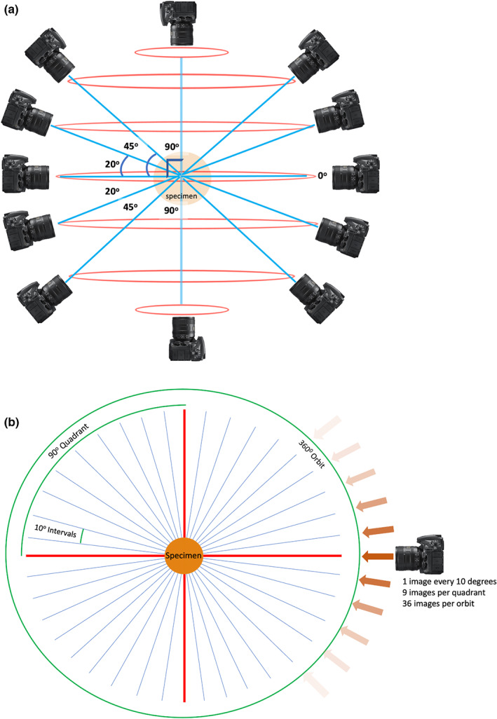
FIGURE 2.

Image acquisition planning. (a) Horizontal orbits (red) and camera angles (blue) used for image acquisition planning, relative to the anatomical specimen in the coronal plane. (b) Image acquisition plan in the transverse plane, that is image capture in one orbit of rotation. Straight red lines represent 90 degree angles, relative to the specimen. Angled blue lines represent camera perspectives.
