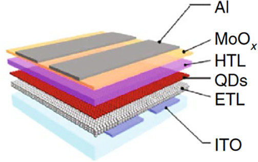
Figure 28.

A schematic depiction of a typical “inverted” QD LED. It comprises an active QD layer sandwiched between ETL and HTL, supplemented by a cathode and an anode. In the present example, the two latter elements are made of an ITO layer and an Al/MoOx bilayer. Reproduced with permission from ref (56) (CC-BY-NC-ND).
