
Figure 39.
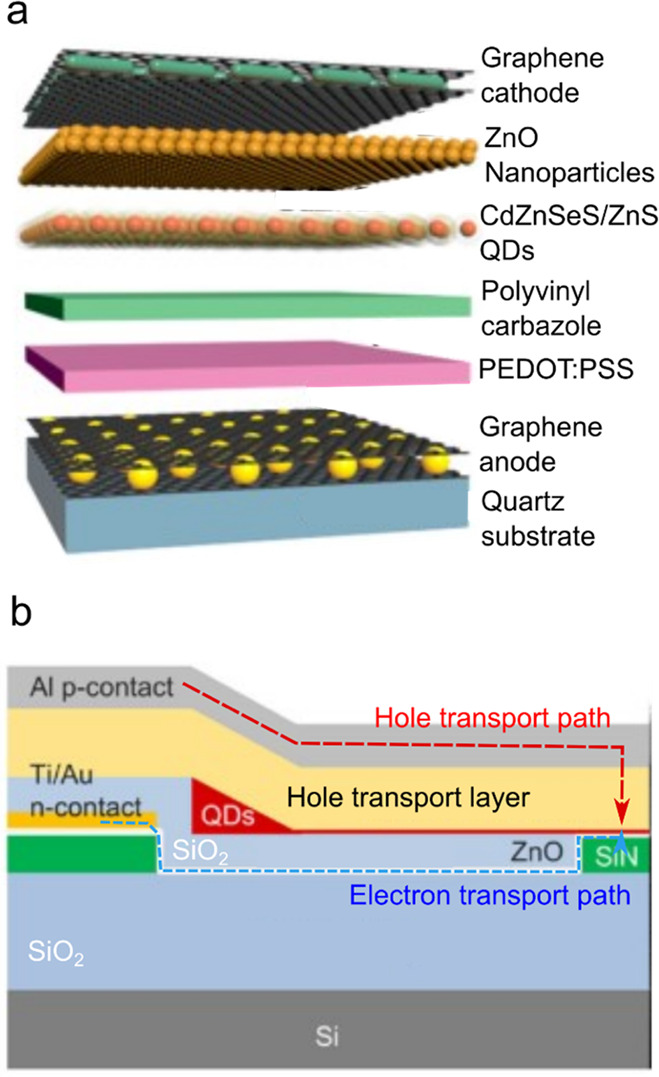
(a) An LED employing graphene layers as both an anode and a cathode. The device stack has the following structure: quartz substrate/graphene/poly(3,4-ethylenedioxythiophene) polystyrenesulfonate (PEDOT:PSS)/polyvinylcarbazole/CdZnSeS/ZnS QDs/ZnO nanoparticles/graphene. Reproduced with permission from ref (283). Copyright 2018 American Chemical Society. (b) A “remote-electrode” approach for suppressing quenching induced by the metal electrode. In this structure, the Ti/Au electron-injecting electrode is laterally displaced from the QD emitting region. The Al hole-injecting contact is followed by a thick hole transport layer. Electrons are delivered via a horizontal charge-transporting channel made of ZnO (depicted as a thin white layer). Blue and red dashed lines are electron and hole transport paths, respectively. Adapted with permission from ref (273). Copyright 2021 Wiley-VCH GmbH.