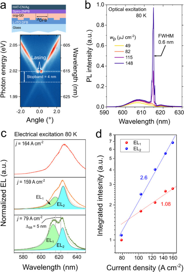
Figure 43.

(a) An LED-like device stack with the 2nd-order DFB grating integrated into the bottom L-ITO electrode (top) and the measurements of its photonic-band structure using a Fourier-plane spectroscopy (bottom). The observed X-shaped pattern is typical of 2nd-order DFB resonators. Lasing manifests as bright spots at the shorter-wavelength edge of the photonic stopband. (b) The pump-fluence-dependent surface-emitted PL spectra of the DFB device from panel (a) exhibit the emergence of a sharp line due to DFB lasing. These data were collected at the LN temperature using excitation with 343 nm, 190 fs pulses. (c) Surface emitted EL spectra of the DFB-cavity based device measured at the LN temperature. When j is increased from 79 to 159 A cm–2, the shorter-wavelength EL feature (EL1), shifted away from the stopband of the DFB-structure, grows linearly, while the emission at the edge of the stopband (EL2) exhibits superlinear growth. This might be indicative of the onset of ASE. However, further increase in j leads to broadening and a redshift of the EL spectrum due to strong device overheating, which likely suppresses the development of laser action. (d) The EL2 intensity (IEL2) shows a superlinear growth with increasing j (IEL2 ∝ j2.6), while the growth of the EL1 feature (IEL1) is nearly linear (IEL1 ∝ j1.08). These behaviors might suggest the development of ASE due to the stopband-edge mode. Adapted with permission from ref (17) (CC-BY 4.0).
