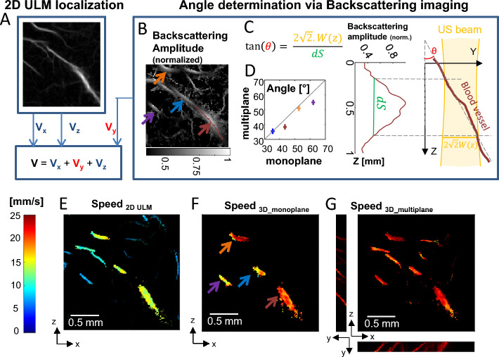
Figure 5.
Backscattering imaging and speed vector correction. (A–D) Schematic of the speed vector correction: (A) Vx and Vy are estimated thanks to 2D ULM while Vy is estimated thanks to ULM backscattering imaging (B) Arrows depict selected vessels for (D). (C) Blood vessel angle θ toward imaging plane is determined using knowledge of the local beam width w(z) and width at half maximum dS of backscattering amplitude function along the vessel. The schematic explains the geometry. (D) Comparison between angle estimation using one plane and multiple planes backscattering information. (E) Speed estimation in classical 2D ULM. (F) Speed estimation correction with ULM backscattering imaging using a single plane. (G) For comparison, speed estimation correction using ULM backscattering imaging information in multiple planes, as done in Fig. 4.

