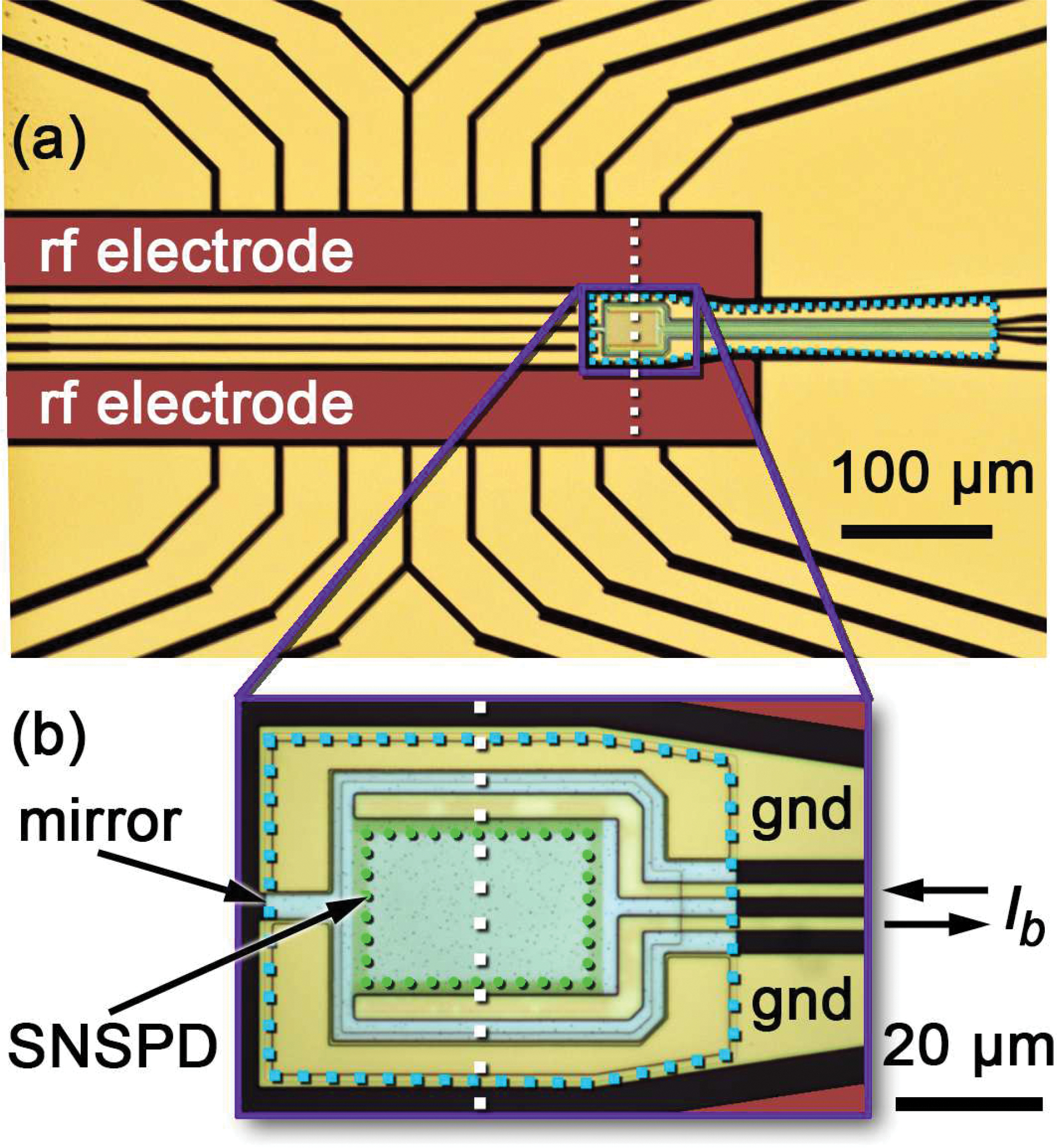
FIG. 1:

Photomicrograph of the linear ion trap with integrated SNSPD. The rf trapping potentials are applied to the labeled and false-colored rf electrodes. All other non-SNSPD electrodes are used for dc trapping potentials. The magnified inset (b) shows a trap design where the SNSPD is on top of a small aluminum mirror, while a larger aluminum mirror spanning the region beneath the leads of the SNSPD can be seen in a different trap design shown in panel (a). Both mirrors appear light blue in the gaps between gold electrodes and are surrounded by a light blue dotted line, while the black gaps show the substrate. The green dotted line in (b) borders the active area of the SNSPD. The white dashed lines indicate the plane of the 2D simulations in Fig. 2. The bias current Ib is applied to the leads of the SNSPD. The electrodes labeled “gnd” are electrically connected to the mirror and can be connected to ground.
