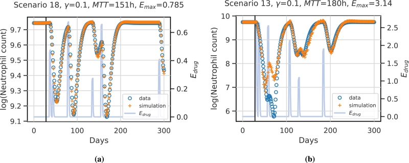
Figure 6.
Example simulations of test scenarios for two different virtual patients/scenarios. The vertical black line indicates the prediction start. Values before this time point are assumed constant and are used to initiate the network. Data points are derived from the mechanistic simulation and are shown in blue circles. Network prediction is marked by orange crosses. The function representing the therapy effect is displayed in light blue. (a) shows the best predicted patient and scenario (scenario 18). The patient is characterised by the parameters γ = 0.1,  and Emax = 0.785. (b) shows the worst approximation, which corresponds to scenario 13 and patient parameter settings of γ = 0.1,
  and Emax = 3.14. Note that y-axes differ between the two patients.

