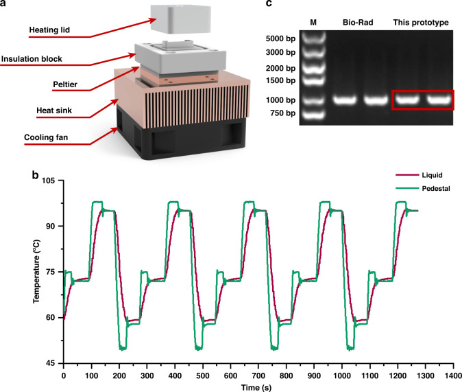
Fig. 3. PCR module.
a Structure of the PCR module, including a cooling fan, a heat sink, a Peltier thermoelectric cooling effect element, an insulation block, a reaction tube, and a heating lid. b Real-time temperature curves in PCR (red for liquid and green for tube pedestal). c Electrophoresis image after PCR, where samples were loaded in the following order: marker, PCR products from the standard machine, and PCR products from this platform

