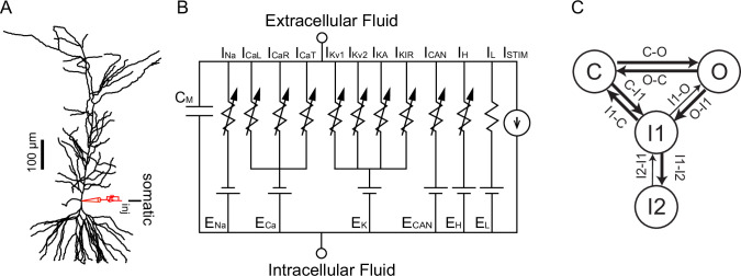
Figure 11. Model Schematics.
(A) Reconstructed morphology ported to NEURON simulation program, with somatic current injection site labeled. (B) Equivalent circuit diagram, with the reversal potentials for each channel indicated by EX. The following currents were modeled using Ohmic drive and conductances in parallel with a membrane capacitance (CM): a Na+ current (INa), L-type (ICaL), R-type (ICaR), and T-type (ICaT) Ca2+ currents, two delayed rectifiers (IKv1 and IKv2), an A-type K+ current (IA), an inward rectifying K+ current (IKIR), a nonspecific Ca2+-activated current (ICAN), a hyperpolarization-activated mixed cationic h-current (Ih), and a leak current (IL). (C) Markov Model of the NaV channel with an open state (O), a closed state (C), a short-term inactivated state (I1) and a long-term inactivated state (I2). See also Figure 11—figure supplement 1.


